Transport Rails Module.pdf - 第14页
TRANSPORT RAILS MODULE ADJUSTMENTS AND SETTINGS 16.14 Technical Reference Manu al Chapter Issue 4 Jan 10 Rear Rail Parallelism W ARNING BOARD CLAMPS. EXTREME CA RE MUST BE EXERCISED W HEN WORKING IN THE TOOLING AREA OF T…

TRANSPORT RAILS MODULE
ADJUSTMENTS AND SETTINGS
Chapter Issue 4 Jan 10 Technical Reference Manual 16.13
40. Recheck the parallelism as detailed in Step 32.
41. Tighten the bolts slackened in Steps 34 to 36.
42. Recheck the parallelism as detailed in Step 32.
43. When the adjustment is complete, remove the board edge guides from each
end of the rail.
44. Remove each bolt disturbed (one at a time), apply a suitable locking
compound and fully tighten.
45. Refit the board edge guide to each end of the rail.
46. Remove the rail setting jig from the rising table.
47. Fit the board clamp to the front rail.
48. Close the front printhead cover.
49. Press the System button.
50. Select Exit.
51. Select Exit.
52. Select Back.
TRANSPORT RAILS MODULE
ADJUSTMENTS AND SETTINGS
16.14 Technical Reference Manual Chapter Issue 4 Jan 10
Rear Rail Parallelism
WARNING
BOARD CLAMPS. EXTREME CARE MUST BE EXERCISED WHEN WORKING IN
THE TOOLING AREA OF THE MACHINE TO AVOID INJURY. THE FOILS ON THE
FRONT AND REAR BOARD CLAMPS ARE VERY SHARP.
NOTE
Ensure Front Rail Parallelism has been carried out prior to commencing this
procedure. It is recommended this procedure is carried out by two persons.
1. Select Shut Down.
2. Select Continue.
3. Switch the mains isolator to OFF.
4. Remove the left and right machine side panels.
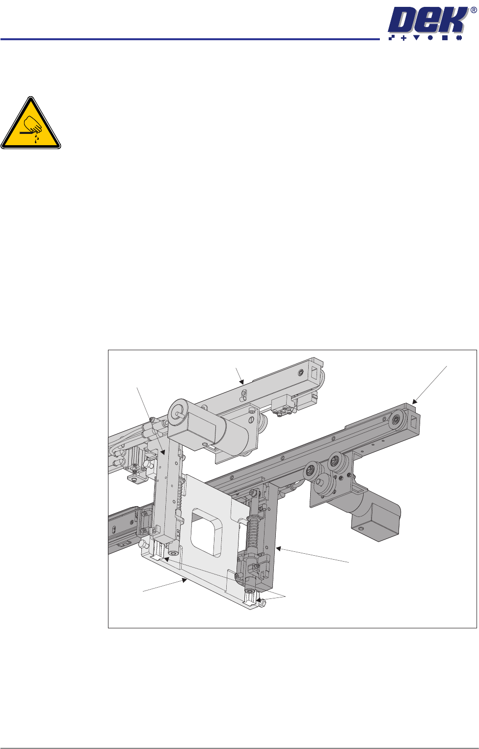
5. Using a pair of rail parallelism H jigs (DEK Part No. 158109) fit the jigs to the
front transport rail left and right leg linear guides. Ensure the linear guides
fit snugly in the jig slots.
6. Move the rear transport rail forwards, towards the front rail, until the rear leg
linear guides fit into the slots of the H jigs.
7. If both sets of linear guides fit snugly in the slots of the jigs, the rear transport
rail is parallel to the front rail, go to Step 15.
Front Rail
Rear Rail
Linear Guide Rails
Rear Right Transport Rail Leg
H Jig
View on Front Right Hand Side
Front Right
Transport
Rail Leg
TRANSPORT RAILS MODULE
ADJUSTMENTS AND SETTINGS
Chapter Issue 4 Jan 10 Technical Reference Manual 16.15
8. Remove the H jigs and carry out the Front Rail Parallelism check as detailed
earlier in this chapter.
9. Refit the H jigs.
10. If both sets of linear guides fit snugly in the slots of the jigs, the rear transport
rail is parallel to the front rail, go to Step 15.
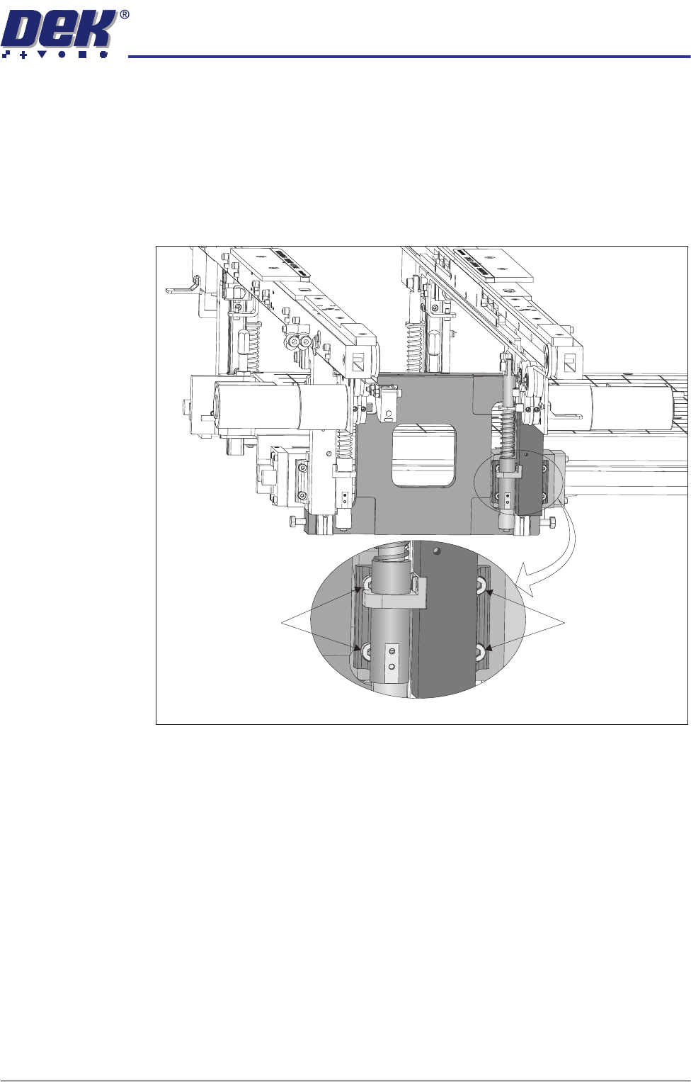
11. Loosen the four bolts securing the rear right hand side rail leg to the bearing
block.
12. Repeat Step 11 on the left hand side.
13. Reposition the rear rail until the linear guides fit snugly in the jig slots.
14. Tighten all eight securing bolts loosened in Steps 11 and 12.
15. Remove the H jigs.
16. Refit the machine panels removed in Step 4.
View on Right Hand Side of Transport Rails
Securing Bolts Securing Bolts