Transport Rails Module.pdf - 第21页
TRANSPORT RAILS MODULE ADJUSTMENTS AND SETTINGS Chapter Issue 4 Jan 10 Technical Reference Manu al 16.21 14. Select Run Diagnost . 15. Open the front printhead cover . 16. Adjust the two downstop screws on the snugger b …
TRANSPORT RAILS MODULE
ADJUSTMENTS AND SETTINGS
16.20 Technical Reference Manual Chapter Issue 4 Jan 10
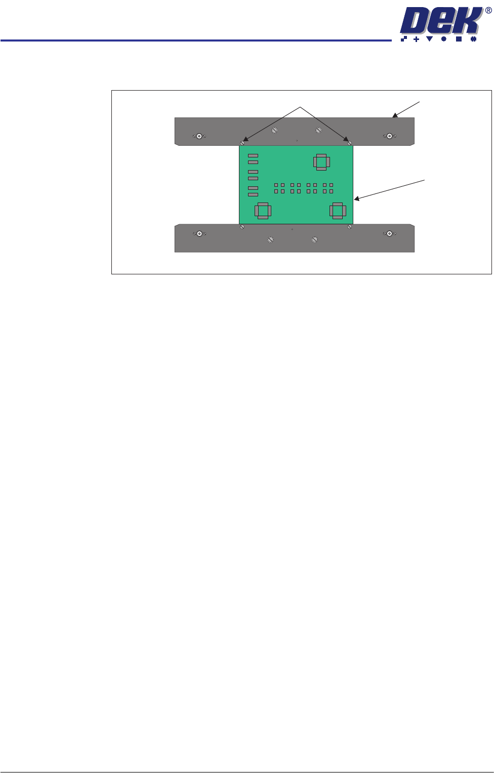
16. Adjust the two downstop screws on each foil-less clamp so that the top of
the board and the foil-less clamps are aligned.
17. Close the front printhead cover.
18. Press the System button.
19. Select Run Diagnost.
20. Open the front printhead cover.
21. Remove the product board from the machine.
22. Refit the screen.
23. Close the front printhead cover.
24. Press the System button.
25. Select Exit.
26. Select Exit.
27. Select Back.
Snugger Base
Plate Height
Adjustment
The snugger base plate and the front snugger plate are height adjustable to
accommodate for different board thicknesses.
1. Select Open Cover Commands.
2. Select Carriage To Rear.
3. Select Unload Screen.
4. Open the front printhead cover.
5. Remove the screen from the machine.
6. Place a product board centrally between the snuggers.
7. Close the front printhead cover.
8. Press the System button.
9. Select Maintenance.
10. Select Diagnostics.
11. Use Next or Previous to highlight Rail System.
12. Select Select Module.
13. Use Next or Previous to highlight Toggle Board Clamp.
Downstop Screw
Foil-less Clamp
Product Board
Plan View of Foil-less Clamps
TRANSPORT RAILS MODULE
ADJUSTMENTS AND SETTINGS
Chapter Issue 4 Jan 10 Technical Reference Manual 16.21
14. Select Run Diagnost.
15. Open the front printhead cover.
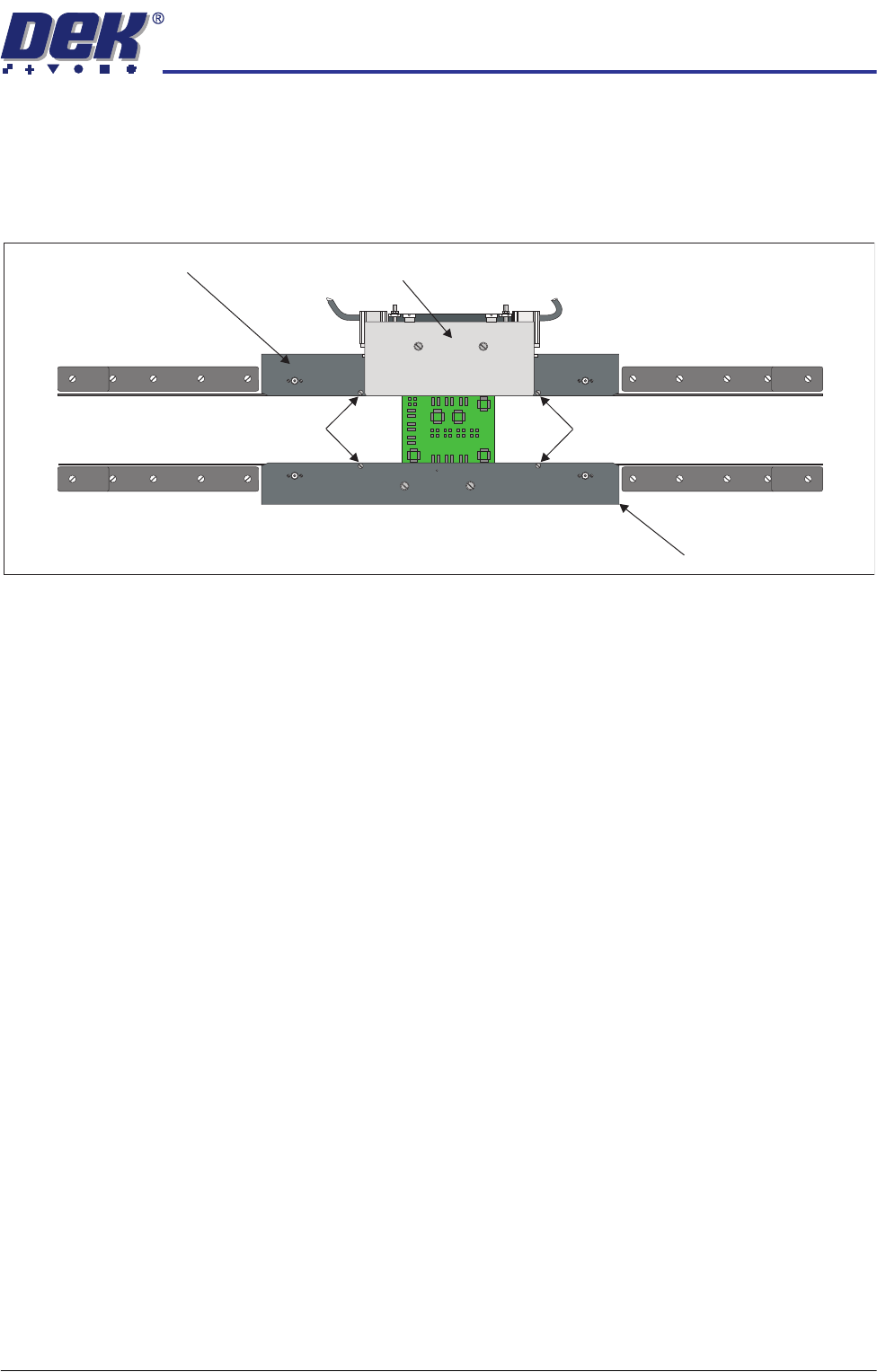
16. Adjust the two downstop screws on the snugger base plate so that the top
of the board and the rear snugger plate are aligned.
17. Adjust the two downstop screws on the front snugger plate so that the top
of the board and the front snugger plate are aligned.
18. Close the front printhead cover.
19. Press the System button.
20. Select Toggle Board Clamp.
21. Select Run Diagnost.
22. Open the front printhead cover.
23. Remove the product board from the machine.
24. Refit the screen.
25. Close the front printhead cover.
26. Press the System button.
27. Select Exit.
28. Select Exit.
29. Select Back.
Rear Snugger
Plate Parallelism
1. Select Open Cover Commands.
2. Select Carriage To Rear.
3. Select Unload Screen.
4. Open the front printhead cover.
5. Remove the screen from the machine.
Downstop Screws
Downstop Screws
Rear Snugger Plate
Front Snugger Plate
Plan View of Rail System
Snugger Base Plate
TRANSPORT RAILS MODULE
ADJUSTMENTS AND SETTINGS
16.22 Technical Reference Manual Chapter Issue 4 Jan 10
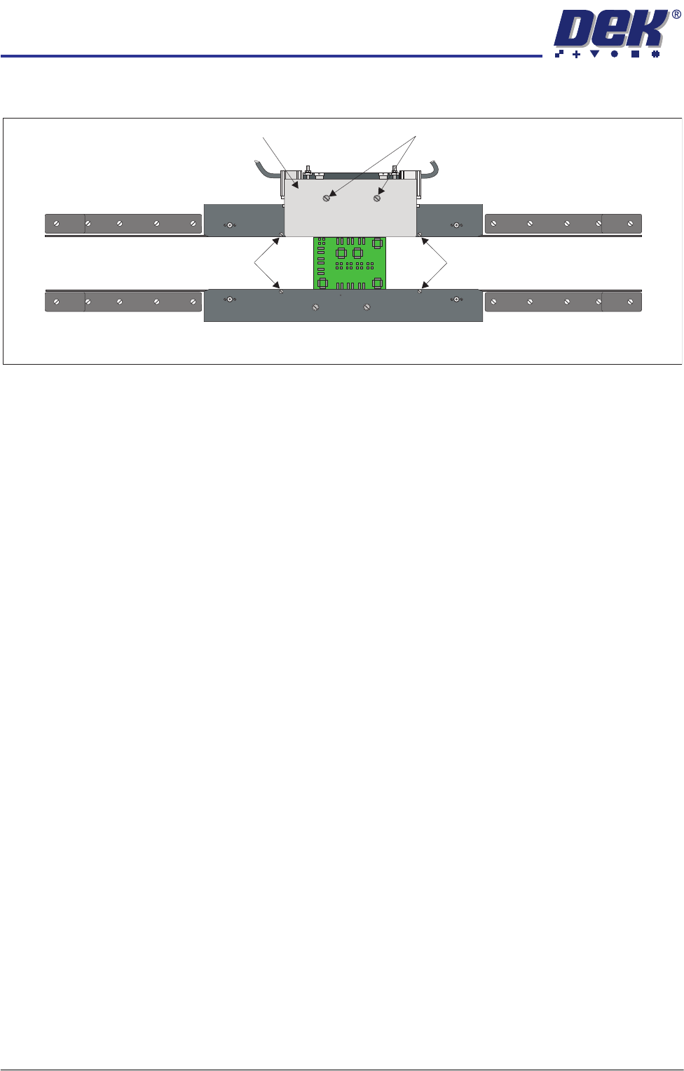
6. Slacken the two rear snugger plate securing screws.
7. Place a product board centrally between the snuggers.
8. Close the front printhead cover.
9. Press the System button.
10. Select Maintenance.
11. Select Diagnostics.
12. Use Next or Previous to highlight Rail System.
13. Select Select Module.
14. Use Next or Previous to highlight Toggle Board Clamp.
15. Select Run Diagnost.
16. The edge of the rear snugger plate aligns with the edge of the board.
17. Open the front printhead cover.
18. Tighten the two rear snugger plate securing screws.
19. Close the front printhead cover.
20. Press the System button.
21. Select Run Diagnost.
22. Open the front printhead cover.
23. Remove the product board from the machine.
24. Refit the screen.
25. Close the front printhead cover.
26. Press the System button.
27. Select Exit.
28. Select Exit.
29. Select Back.
Home Position
Rail Width Check
Ensure that the board clamps are fitted and that the Board Clamp Setting
procedure (this section refers) has been completed before carrying out the
following procedure:
1. Select Open Cover Commands.
Downstop Screws
Downstop Screws
Rear Snugger Plate Rear Snugger Plate Securing Screws
Plan View of Rail System