Transport Rails Module.pdf - 第27页
TRANSPORT RAILS MODULE ADJUSTMENTS AND SETTINGS Chapter Issue 4 Jan 10 Technical Reference Manu al 16.27 36. There are two Rail to T able Height Setting Kits: • 193177 for use with transpo rt rails with round belt s (red…

TRANSPORT RAILS MODULE
ADJUSTMENTS AND SETTINGS
16.26 Technical Reference Manual Chapter Issue 4 Jan 10
26. Select Exit.
27. Use Next or Previous to highlight Rising Table.
28. Select Select Module.
29. Use Next or Previous to highlight Raise Table to Vision Height.
30. Select Run Diagnost.
31. Select Exit.
32. Use Next or Previous to highlight Rail System.
33. Select Select Module. The board clamps are released.
34. Use Next or Previous to highlight Toggle Board Clamp.
35. Open the front printhead cover.
TRANSPORT RAILS MODULE
ADJUSTMENTS AND SETTINGS
Chapter Issue 4 Jan 10 Technical Reference Manual 16.27
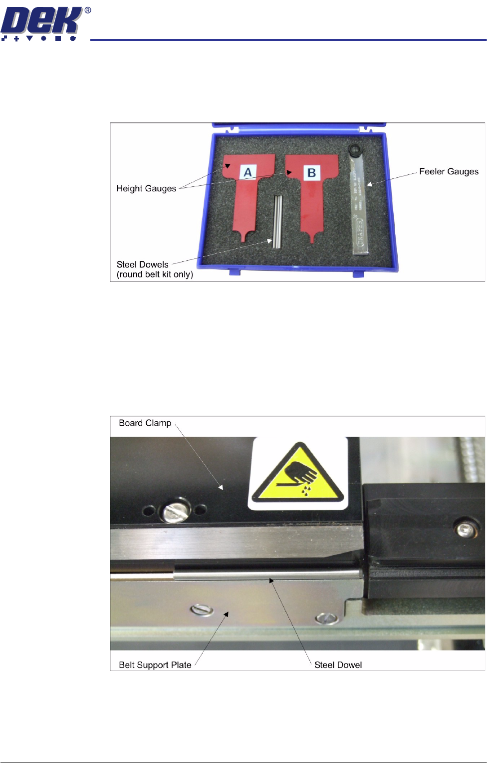
36. There are two Rail to Table Height Setting Kits:
• 193177 for use with transport rails with round belts (red height gauges)
• 193178 for use with transport rails with flat belts (blue height gauges)
37. Check which type of transport belts are on the machine and select the
appropriate kit.
38. If the machine has transport rails with flat belts, go to Step 47.
39. Remove the transport belt from the front rail.
40. Remove two steel dowels from the kit.
41. Place a steel dowel on the front belt support plate aligning with the edge of
the board clamp.
42. Place another steel dowel on the belt support plate aligning with the other
end of the board clamp.
43. Remove the two height gauges from the kit.
TRANSPORT RAILS MODULE
ADJUSTMENTS AND SETTINGS
16.28 Technical Reference Manual Chapter Issue 4 Jan 10
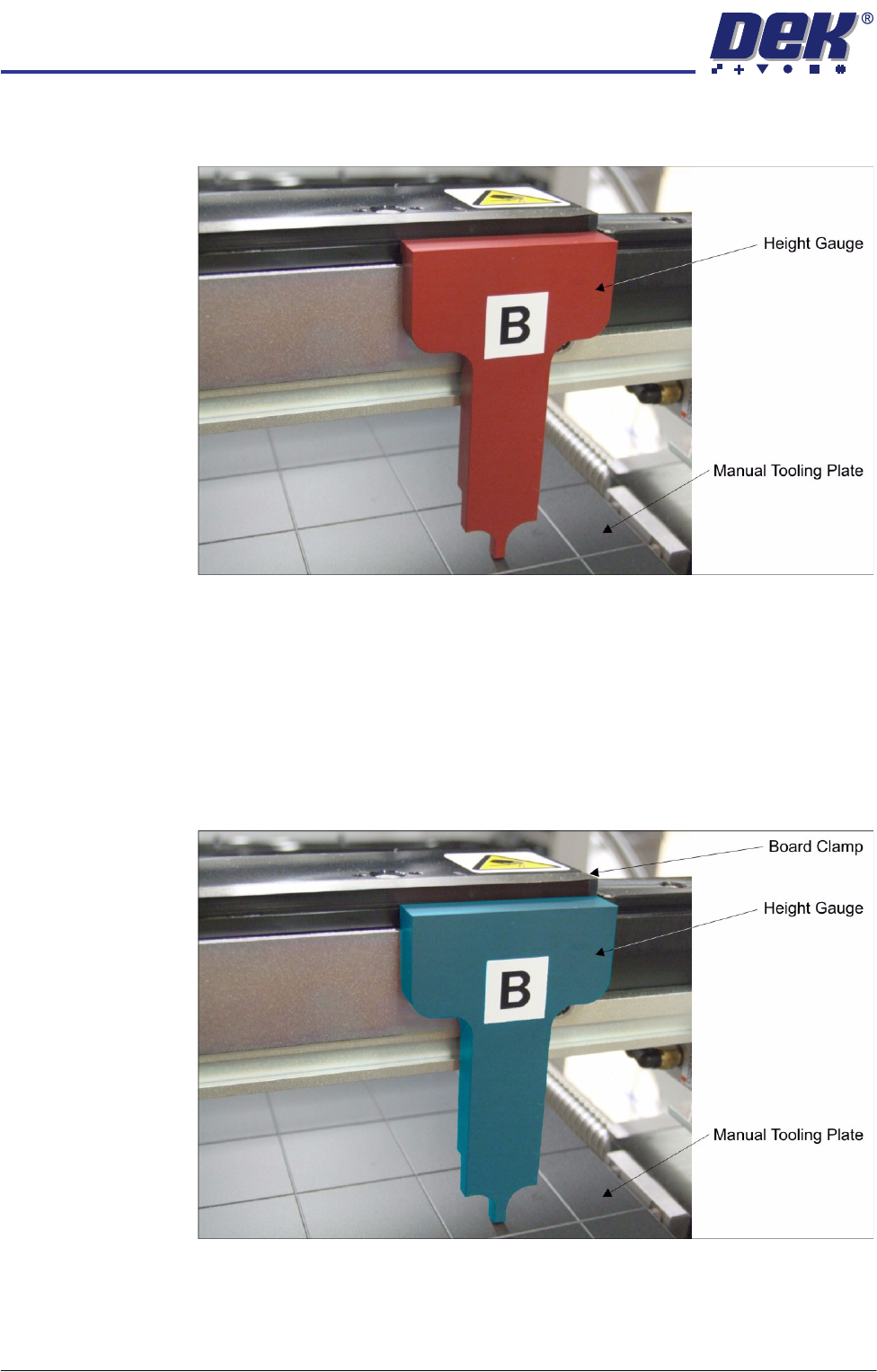
44. Place a height gauge on each of the steel dowels (A on the left and B on the
right).
45. Using the feeler gauges, ensure that the height gauge is not touching the
manual tooling plate.
46. Go to Step 52.
47. Manually move the front transport belt so that joint in the belt is over the drive
pulley.
48. Move the belt backwards and forwards to even out the belt tension.
49. Place a height gauge on top of the front transport belt aligned to the edge of
the board clamp (A on the left and B on the right).
50. Place a height gauge on top of the transport belt at the other edge of the
board clamp.
51. Using the feeler gauges, ensure that the height gauge is not touching the
manual tooling plate.