Transport Rails Module.pdf - 第3页
TRANSPORT RAILS MODULE OVERVIEW Chapter Issue 4 Jan 10 Technical Reference Manu al 16.3 Figure 16-1 Board Clamping Arrange ment s Board T ransport Belts Rear Board Clamp Board Clamps Board T ransport Belts Rear Snugger P…

TRANSPORT RAILS MODULE
OVERVIEW
16.2 Technical Reference Manual Chapter Issue 4 Jan 10
The transport rails are a programmable width conveyor system set by the board
width parameter in the product file. The rails transport the board using belts
from the upline machine, into this machine, where the board is positioned,
clamped and printed. After printing the board is transferred using the same belts
to the downline machine.
The heavy board transport rails can transport boards up to 6kg. This is achieved
using an extra drive pulley on each rail and flat profiled transport belts.
NOTE
1. To prevent damage to the camera board stop the remote board stop must
be used for product boards over 1kg in weight.
2. Information on the remote board stop is detailed in the Rising Table chapter
of this manual.
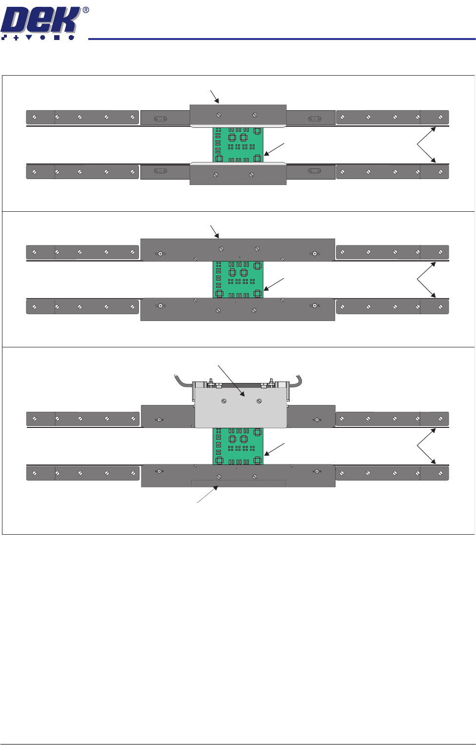
The transport rails can be fitted with one of the following board clamping
arrangements:
• 250mm or 500mm Board Clamps
• 250mm or 500mm Foil-less Clamps
• Board Snugger Assembly
Foil-less clamps are utilized for thin pliable boards where there is a requirement
to print close to the board edge. The foil-less clamps are assisted with the use
of a vacuum box beneath the product board.
Board snuggers are an alternative to the standard board clamps and are utilized
when there is a requirement to print close to the board edge.
TRANSPORT RAILS MODULE
OVERVIEW
Chapter Issue 4 Jan 10 Technical Reference Manual 16.3
Figure 16-1 Board Clamping Arrangements
Board
Transport Belts
Rear Board Clamp
Board Clamps
Board
Transport Belts
Rear Snugger Plate
Counterweight Block
Board Snuggers
Board
Transport Belts
Rear Foil-less Clamp
Foil-less Clamps
TRANSPORT RAILS MODULE
ELECTRICAL SCHEMATIC
16.4 Technical Reference Manual Chapter Issue 4 Jan 10
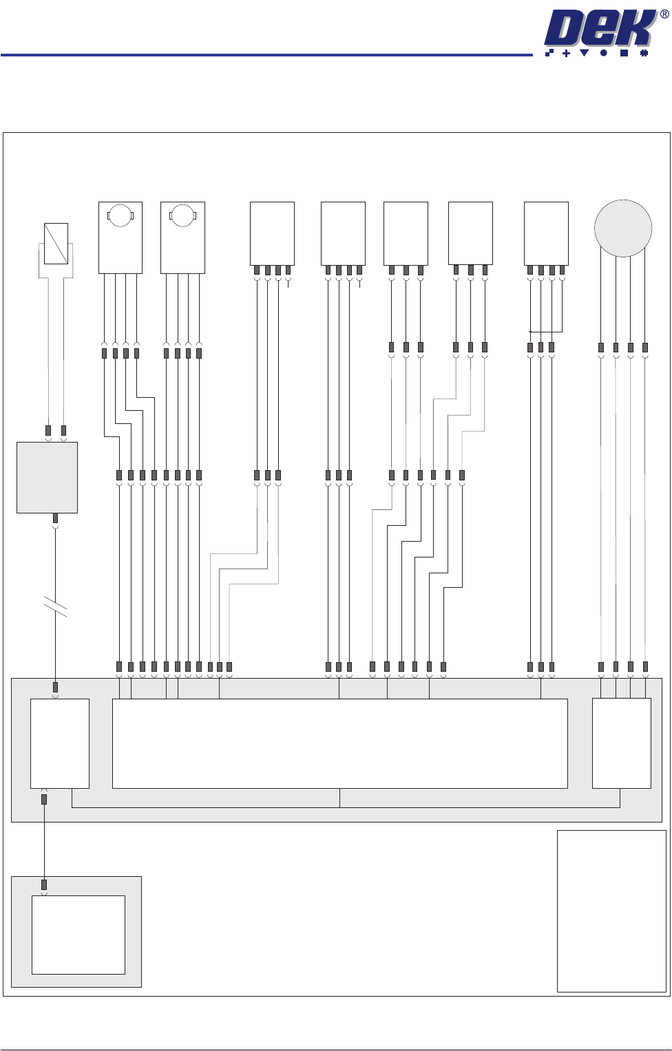
ELECTRICAL SCHEMATIC
Machine PC
Motherboard
Machine Control Enclosure
Front Belt
Drive (8M03)
Rear Belt
Drive (8M04)
DIG IN 10
DIG IN 11
Rail Lift Left
(8SE5)
Board at Right
Sensor (8SE7)
Board at Left
Sensor (8SE8)
8PL10
8PL04
M36PL17
8PL03
Sig
Sig
+12V
+12V
+12V
(L)
0V
0V
8PL12
DIG IN 6
Sig
0V
M36PL22
Moving Rail
Stepper
Motor 2B-
Motor 2A-
Motor 2B+
Motor 2A+
8PL20
8M2
Dual Stepper
X3
NextMove
Interface Card
X4
M
Enable
Direction
24V SW
0V
M
Enable
Direction
24V SW
0V
8SK21
8PL22
8SK23
M36PL18
!DIG OUT 3
DIG OUT 3
DIG OUT 2
DIG OUT 2
NextMove ES
(I/O Node 1)
X5
Board Clamp/
Snugger Solenoid
(16SOL10)
DIG OUT 9
GND
Main Machine
I/O Node 2
N2PL4
CAN Bus
N2SK2
USB
Moving Rail
Home (8SE6)
8PL26
M36PL19
+12V
0V
Sig
DIG IN 5
Rail Lift Right
(8SE4)
+12V
(L)
8PL15
DIG IN 7
Sig
0V
NOTE
The breaks in the CAN Bus
chain reflect that additional
I/O Nodes may be fitted,
refer to Machine Control
chapter for the complete
CAN Bus chain.
N/C
N/C
(L)