Transport Rails Module.pdf - 第40页
TRANSPORT RAILS MODULE REPLACEMENT PROCEDURES 16.40 Technical Reference Manu al Chapter Issue 4 Jan 10 of the nut at the front face of the rail drive plate. 2. Slide the adjustab le idler pulley to slacken the drive belt…
TRANSPORT RAILS MODULE
REPLACEMENT PROCEDURES
Chapter Issue 4 Jan 10 Technical Reference Manual 16.39
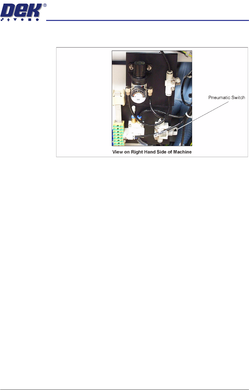
14. Locate the magnetic plate on the right hand side of the machine containing
the pneumatics for the snuggers.
15. Turn the pneumatic switch On.
16. Select Maintenance.
17. Select Machine Setup.
18. Select Basics.
19. Select Clamp Type.
20. Select Board Clamps.
21. Select Accept.
22. Select Back.
23. Select Back.
24. Select Back.
25. This completes the procedure if board clamps have been fitted. If foil-less
clamps have been fitted continue with Step 26.
26. Carry out Foil-less Clamp Height Adjustment in the Adjustments and Set-
tings section of this chapter.
NOTE
The Board Clamp Setting procedure is not required after snugger to board
clamp/foil-less clamp replacement.
Rear Rail Drive
Belt
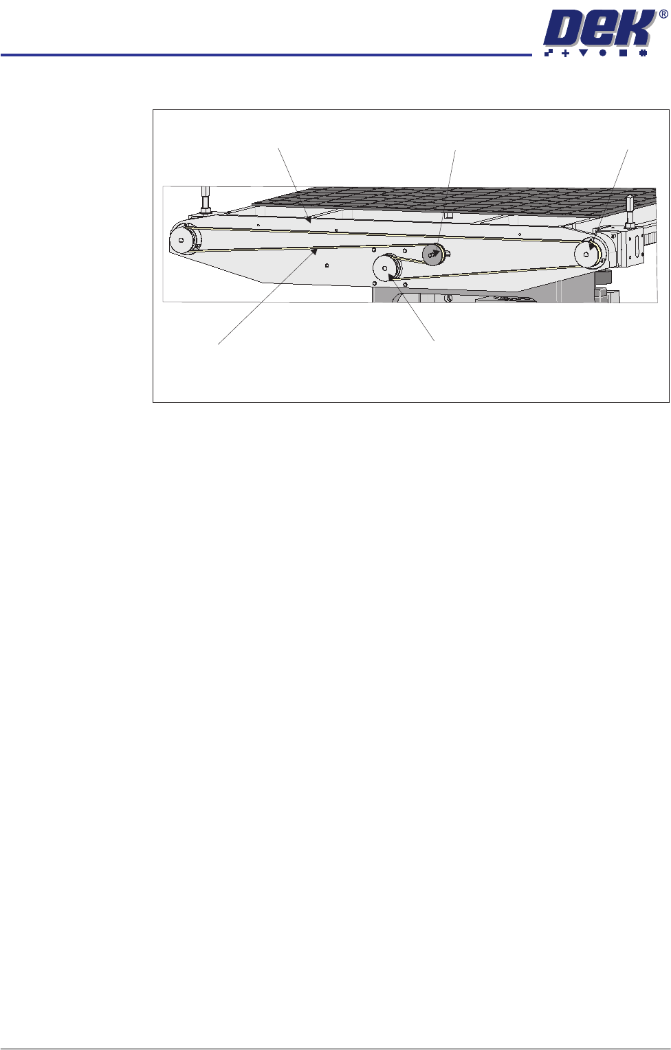
1. At the rear of the rising table, slacken the adjustable idler pulley by means
TRANSPORT RAILS MODULE
REPLACEMENT PROCEDURES
16.40 Technical Reference Manual Chapter Issue 4 Jan 10
of the nut at the front face of the rail drive plate.
2. Slide the adjustable idler pulley to slacken the drive belt.
3. Remove the drive belt and discard.
4. Fit the replacement drive belt.
5. Using a suitable cable tie, engage a forcemeter with the adjustable idler
pulley. Apply a horizontal force of 6kg.
6. Maintaining this force, tighten the adjustable idler pulley securing nut.
7. Using a tension meter on the top of the drive belt, check the tension is
38Hz to 45Hz.
8. Adjust the drive belt tension as necessary to achieve the reading in Step 7.
9. Select Maintenance.
10. Select Diagnostics.
11. Use Next or Previous to highlight Rail System.
12. Select Select Module.
13. Use Next or Previous to highlight Drive Rail Width Using Two Button
Control.
14. Select Run Diagnost.
15. Using the left jog button drive the rear rail to the rear for a few seconds to
even out the tension in the belt.
16. Repeat Steps 7 and 8.
17. Select Exit.
18. Select Exit.
19. Select Back.
Heavy Board
Rails Drive Belt
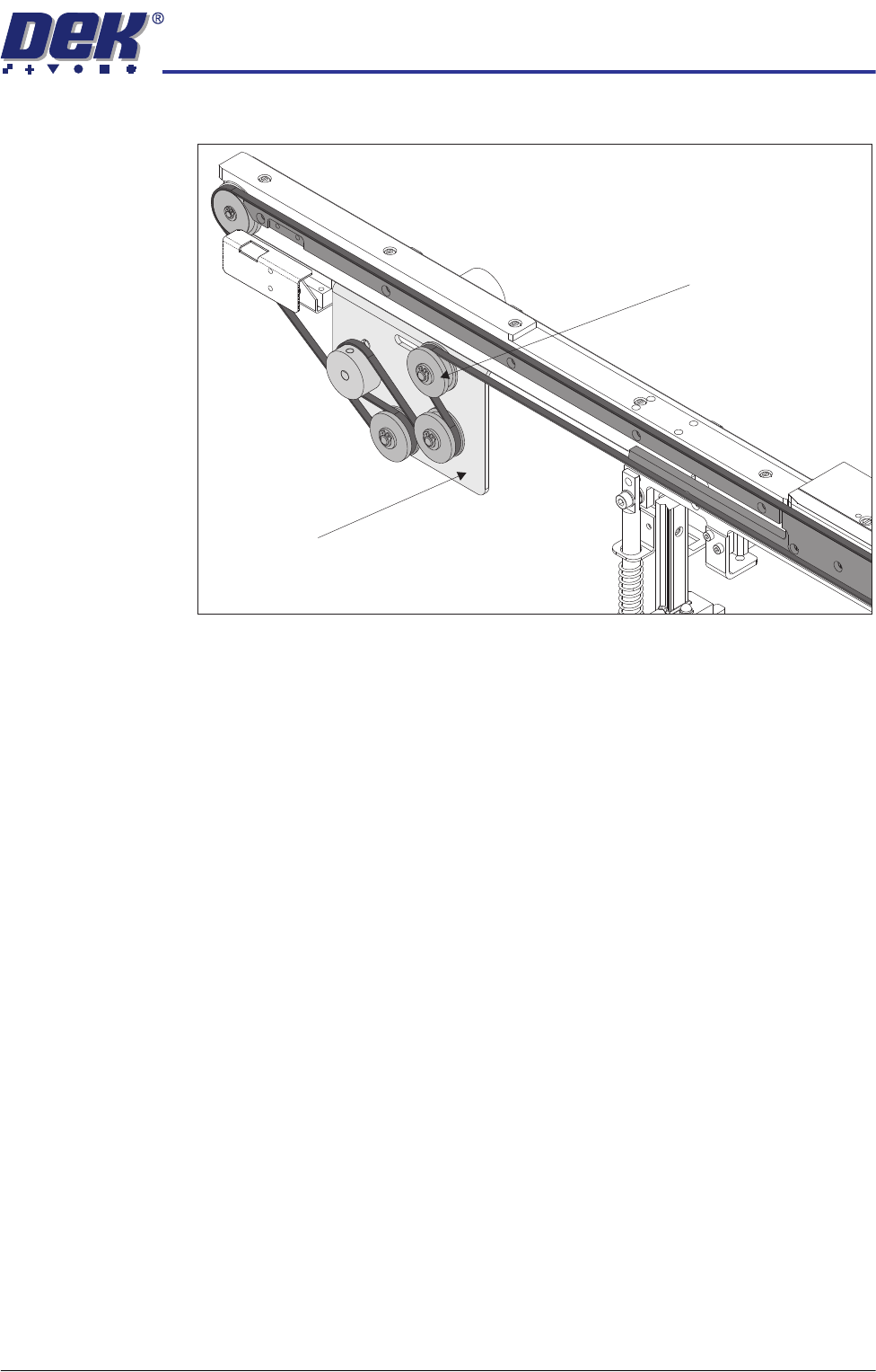
1. Slacken the adjustable idler pulley securing screw, at the rear of the motor
View on Rear of Rising Table
Adjustable Idler Pulley
Moving Rail Stepper Motor Pulley
Drive Belt
Left Hand Drive Shaft
Rail Drive Plate
TRANSPORT RAILS MODULE
REPLACEMENT PROCEDURES
Chapter Issue 4 Jan 10 Technical Reference Manual 16.41
bracket.
2. Slide the adjustable idler pulley to slacken the drive belt.
3. Remove the drive belt and discard.
4. Fit the replacement drive belt.
5. Using a suitable cable tie, engage a forcemeter with the adjustable idler
pulley. Apply a horizontal force of 5.1kg to 6.1kg.
6. Maintaining this force, tighten the adjustable idler pulley securing screw.
7. Select Maintenance.
8. Select Diagnostics.
9. Use Next or Previous to highlight Rail System.
10. Select Select Module.
11. Use Next or Previous to highlight Drive Belts Using Two Button Control.
12. Select Run Diagnost.
13. Using either the left or right jog button, drive the belt motors for a few
seconds to even out the tension in the belt.
14. Recheck the belt tension.
15. Select Exit.
16. Select Exit.
17. Select Back.
View on Inside of Front Rail
Adjustable Idler Pulley
Motor Bracket