Transport Rails Module.pdf - 第41页
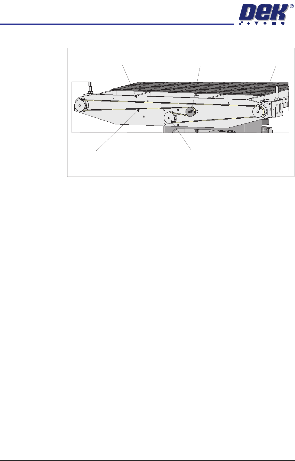
TRANSPORT RAILS MODULE REPLACEMENT PROCEDURES Chapter Issue 4 Jan 10 Technical Reference Manu al 16.41 bracket. 2. Slide the adjustab le idler pulley to slacken the drive belt. 3. Remove the drive belt and discard. 4. Fi…
TRANSPORT RAILS MODULE
REPLACEMENT PROCEDURES
16.40 Technical Reference Manual Chapter Issue 4 Jan 10
of the nut at the front face of the rail drive plate.
2. Slide the adjustable idler pulley to slacken the drive belt.
3. Remove the drive belt and discard.
4. Fit the replacement drive belt.
5. Using a suitable cable tie, engage a forcemeter with the adjustable idler
pulley. Apply a horizontal force of 6kg.
6. Maintaining this force, tighten the adjustable idler pulley securing nut.
7. Using a tension meter on the top of the drive belt, check the tension is
38Hz to 45Hz.
8. Adjust the drive belt tension as necessary to achieve the reading in Step 7.
9. Select Maintenance.
10. Select Diagnostics.
11. Use Next or Previous to highlight Rail System.
12. Select Select Module.
13. Use Next or Previous to highlight Drive Rail Width Using Two Button
Control.
14. Select Run Diagnost.
15. Using the left jog button drive the rear rail to the rear for a few seconds to
even out the tension in the belt.
16. Repeat Steps 7 and 8.
17. Select Exit.
18. Select Exit.
19. Select Back.
Heavy Board
Rails Drive Belt
1. Slacken the adjustable idler pulley securing screw, at the rear of the motor
View on Rear of Rising Table
Adjustable Idler Pulley
Moving Rail Stepper Motor Pulley
Drive Belt
Left Hand Drive Shaft
Rail Drive Plate
TRANSPORT RAILS MODULE
REPLACEMENT PROCEDURES
Chapter Issue 4 Jan 10 Technical Reference Manual 16.41
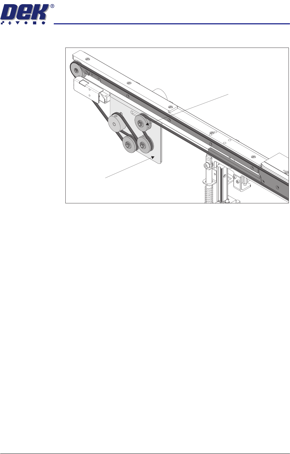
bracket.
2. Slide the adjustable idler pulley to slacken the drive belt.
3. Remove the drive belt and discard.
4. Fit the replacement drive belt.
5. Using a suitable cable tie, engage a forcemeter with the adjustable idler
pulley. Apply a horizontal force of 5.1kg to 6.1kg.
6. Maintaining this force, tighten the adjustable idler pulley securing screw.
7. Select Maintenance.
8. Select Diagnostics.
9. Use Next or Previous to highlight Rail System.
10. Select Select Module.
11. Use Next or Previous to highlight Drive Belts Using Two Button Control.
12. Select Run Diagnost.
13. Using either the left or right jog button, drive the belt motors for a few
seconds to even out the tension in the belt.
14. Recheck the belt tension.
15. Select Exit.
16. Select Exit.
17. Select Back.
View on Inside of Front Rail
Adjustable Idler Pulley
Motor Bracket
TRANSPORT RAILS MODULE
CALIBRATIONS
16.42 Technical Reference Manual Chapter Issue 4 Jan 10
CALIBRATIONS
Board Transport
Belt Speed
The front and rear board transport belts are driven independently by two
variable speed motors. Inevitably one motor drives faster than the other motor.
It is necessary to calibrate these motors so that they drive at the same speed.
Feeder motor speed is measured using a tachometer on the input or output
pulley and adjusted by a potentiometer control on each motor.
Calibration
Procedure
1. Remove the right hand side safety cover to gain access to the transport belt
motors.
2. Select Maintenance.
3. Select Diagnostics.
4. Use Next or Previous to highlight Rail System.
5. Select Select Module.
6. Use Next or Previous to highlight Belt Speed Calibration.
7. Select Run Diagnost.
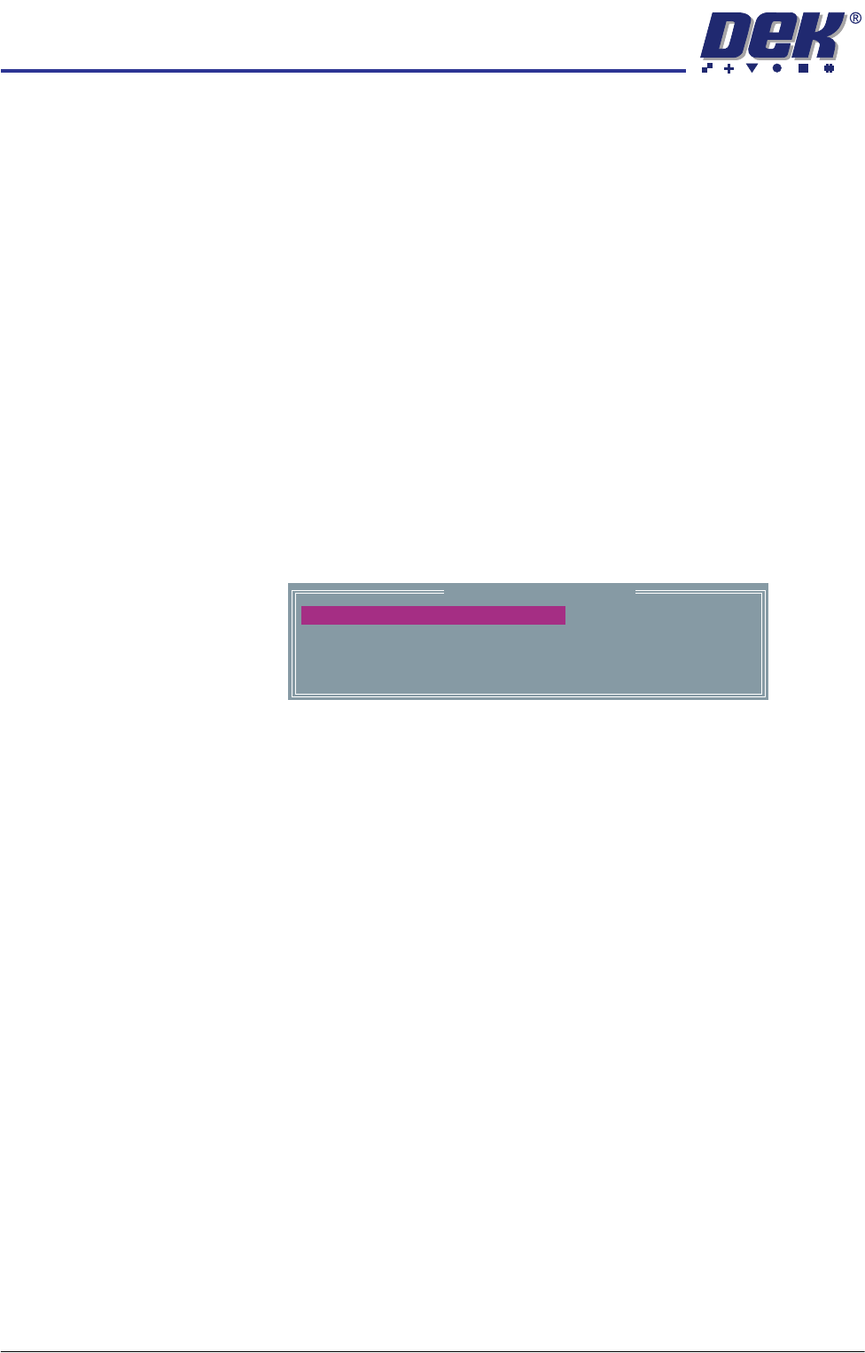
The following window is displayed:
NOTE
Belt Speed Calibration figures displayed on this page have no relevance to
the belt speeds on this machine.
8. Select Incr. or Decr. to start the belts.
Belt Speed Calibration
50000
50000
63999
63999
FRONT R TO L SPEED
FRONT L TO R SPEED
REAR L TO R SPEED
REAR R TO L SPEED