Transport Rails Module.pdf - 第5页
TRANSPORT RAILS MODULE ADJUSTMENTS AND SETTINGS Chapter Issue 4 Jan 10 Technical Reference Manu al 16.5 ADJUSTMENTS AND SETTINGS Rail Lif ted Sensors 1. Select Maintenance . 2. Select Diagnostics . 3. Use Next or Previou…
TRANSPORT RAILS MODULE
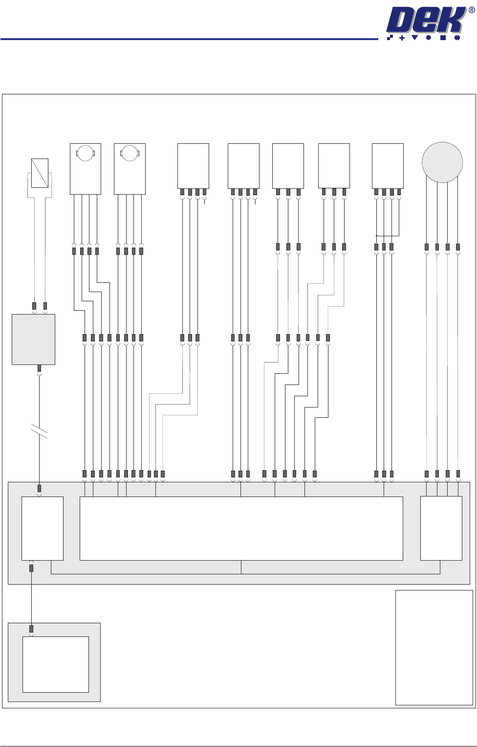
ELECTRICAL SCHEMATIC
16.4 Technical Reference Manual Chapter Issue 4 Jan 10
ELECTRICAL SCHEMATIC
Machine PC
Motherboard
Machine Control Enclosure
Front Belt
Drive (8M03)
Rear Belt
Drive (8M04)
DIG IN 10
DIG IN 11
Rail Lift Left
(8SE5)
Board at Right
Sensor (8SE7)
Board at Left
Sensor (8SE8)
8PL10
8PL04
M36PL17
8PL03
Sig
Sig
+12V
+12V
+12V
(L)
0V
0V
8PL12
DIG IN 6
Sig
0V
M36PL22
Moving Rail
Stepper
Motor 2B-
Motor 2A-
Motor 2B+
Motor 2A+
8PL20
8M2
Dual Stepper
X3
NextMove
Interface Card
X4
M
Enable
Direction
24V SW
0V
M
Enable
Direction
24V SW
0V
8SK21
8PL22
8SK23
M36PL18
!DIG OUT 3
DIG OUT 3
DIG OUT 2
DIG OUT 2
NextMove ES
(I/O Node 1)
X5
Board Clamp/
Snugger Solenoid
(16SOL10)
DIG OUT 9
GND
Main Machine
I/O Node 2
N2PL4
CAN Bus
N2SK2
USB
Moving Rail
Home (8SE6)
8PL26
M36PL19
+12V
0V
Sig
DIG IN 5
Rail Lift Right
(8SE4)
+12V
(L)
8PL15
DIG IN 7
Sig
0V
NOTE
The breaks in the CAN Bus
chain reflect that additional
I/O Nodes may be fitted,
refer to Machine Control
chapter for the complete
CAN Bus chain.
N/C
N/C
(L)
TRANSPORT RAILS MODULE
ADJUSTMENTS AND SETTINGS
Chapter Issue 4 Jan 10 Technical Reference Manual 16.5
ADJUSTMENTS AND SETTINGS
Rail Lifted
Sensors
1. Select Maintenance.
2. Select Diagnostics.
3. Use Next or Previous to highlight Rising Table.
4. Select Select Module.
5. Ensure that Home Rising Table is highlighted.
6. Select Run Diagnost.
7. Select Exit.
8. Use Next or Previous to highlight Rail System.
9. Select Select Module.
10. Ensure that Home Rail Width is highlighted.
11. Select Run Diagnost.
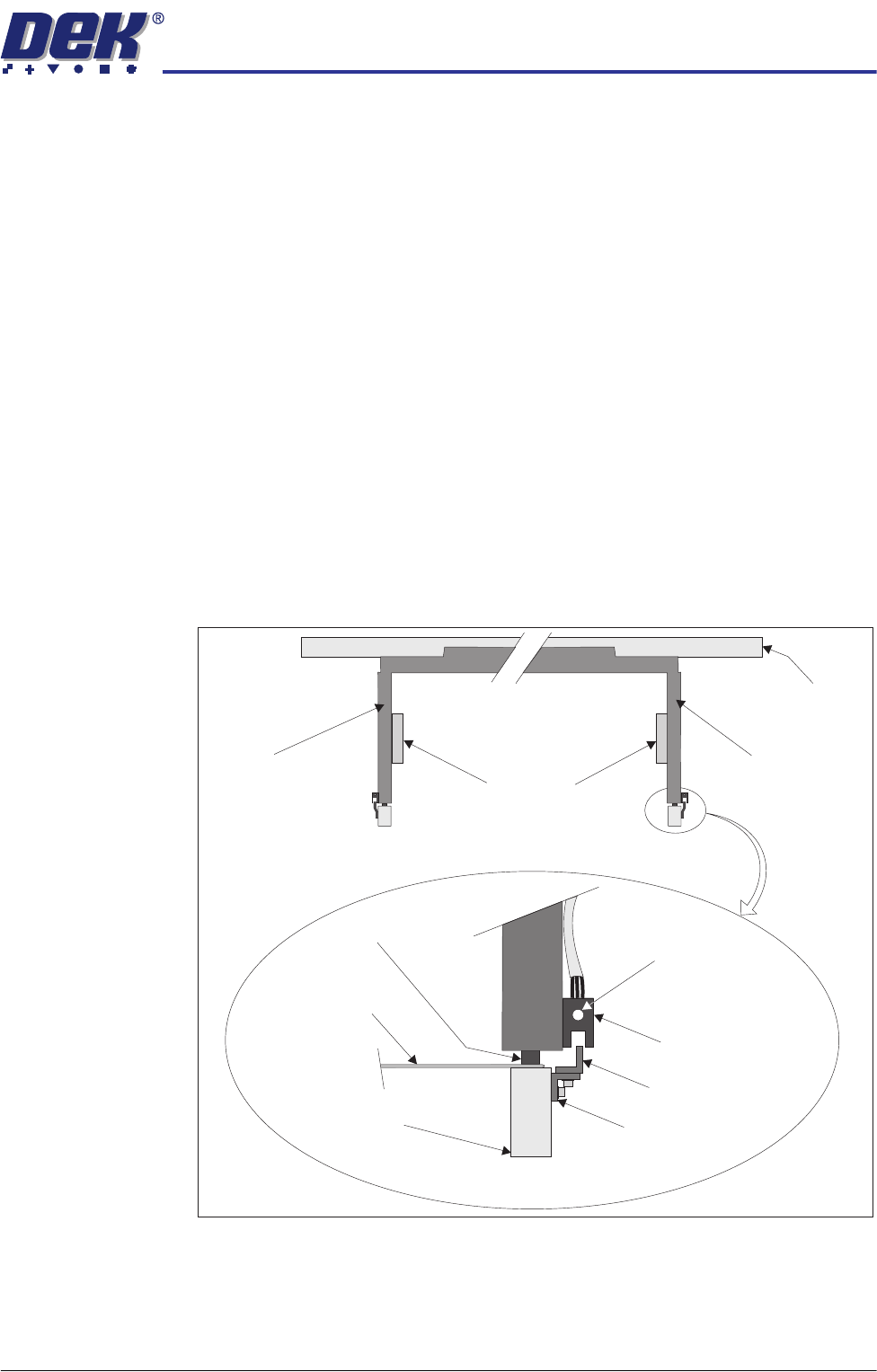
12. Remove the left and right hand safety covers to gain access to the rear rail.
13. Place a 0.5mm feeler gauge between the rail shock absorber on the rear
right rail transport leg and the rail stop bar (clatter bar).
Right Transport Leg
Rear Rail
Front View of Rail System
Left Transport Leg
Linear Bearing
Feeler Gauge
Rail Stop Bar
(Clatter Bar)
Opto Vane
Bracket
Opto Vane
Opto
Shock Absorber
Sensor LED
Enlarged View of Right Rail Opto
TRANSPORT RAILS MODULE
ADJUSTMENTS AND SETTINGS
16.6 Technical Reference Manual Chapter Issue 4 Jan 10
14. Adjust the vane bracket using a 2.5mm Allen key, so that the sensor LED is
Off with a 0.5mm feeler gauge fitted and On with a 0.7mm feeler gauge
fitted.
15. Repeat Steps 13 and 14 for left hand end of the rear rail.
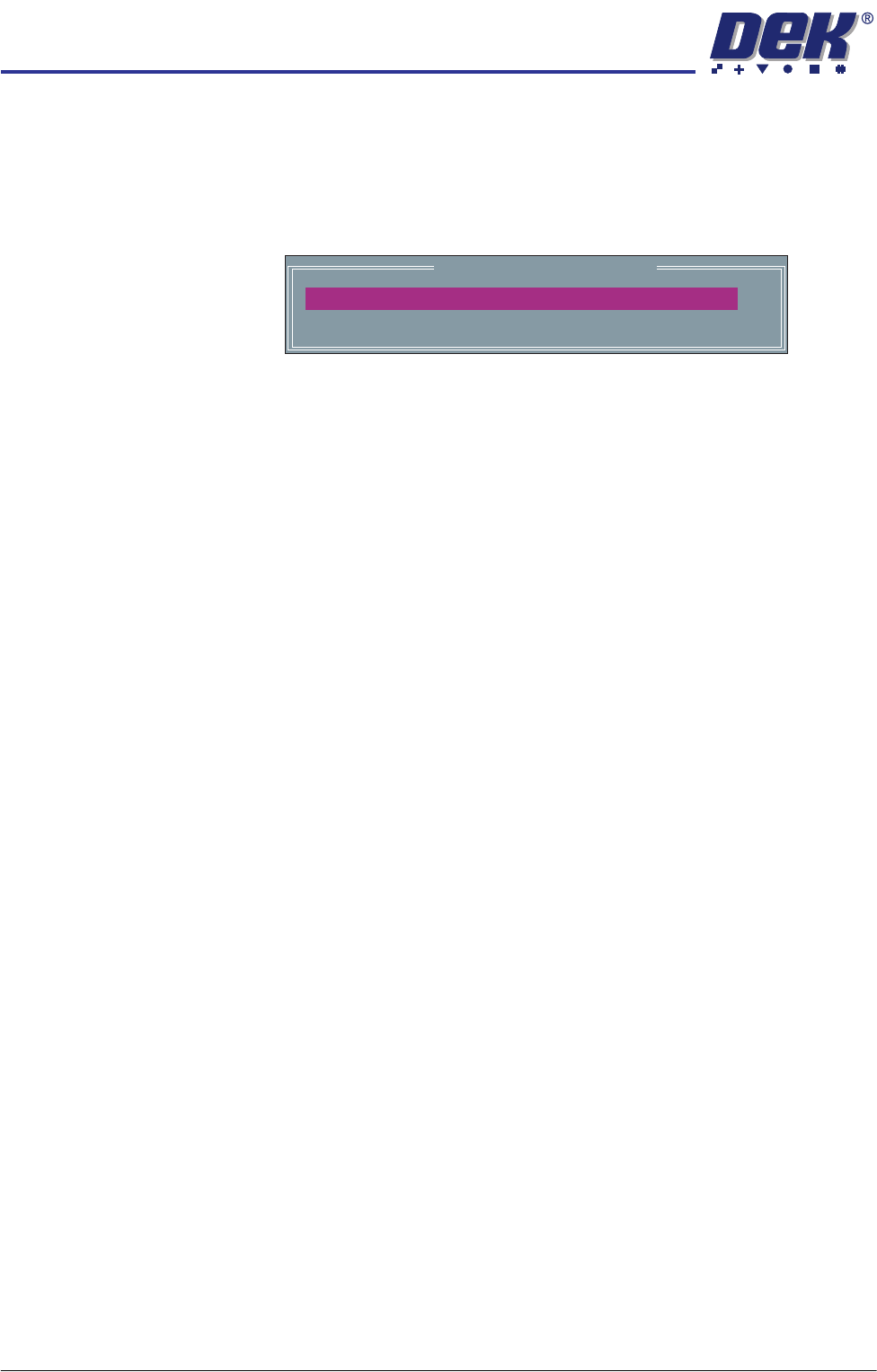
16. Select Adjust, the following window is displayed:
17. Use Incr. or Decr. to set the Board Width to 50mm.
18. Select Exit.
19. Use Next or Previous to highlight Drive Rail To Board Width.
20. Select Run Diagnost.
21. Repeat Steps 13 to 15 for setting the vane at the 50mm width.
22. Use Next or Previous to highlight Home Rail Width.
23. Select Run Diagnost.
24. Repeat Steps 13 to 15 at the home position.
25. Use Next or Previous to highlight Cycle Rails.
26. Select Run Diagnost.
27. Ensure the left and right sensor LED’s remain Off over the full travel of the
rail.
28. Select Stop.
29. Select Exit.
30. Select Exit.
31. Select Back.
Rail System Test Parameters
BOARD WIDTH
CYCLE COUNT
250.0
50
mm
Cycles