Transport Rails Module.pdf - 第7页
TRANSPORT RAILS MODULE ADJUSTMENTS AND SETTINGS Chapter Issue 4 Jan 10 Technical Reference Manu al 16.7 Board at Lef t/ Right Optos The board at lef t/right optos switching threshold can be adjus ted by means of a sensit…
TRANSPORT RAILS MODULE
ADJUSTMENTS AND SETTINGS
16.6 Technical Reference Manual Chapter Issue 4 Jan 10
14. Adjust the vane bracket using a 2.5mm Allen key, so that the sensor LED is
Off with a 0.5mm feeler gauge fitted and On with a 0.7mm feeler gauge
fitted.
15. Repeat Steps 13 and 14 for left hand end of the rear rail.
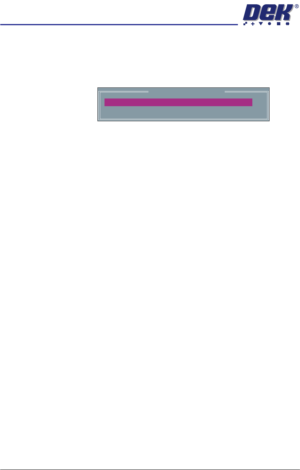
16. Select Adjust, the following window is displayed:
17. Use Incr. or Decr. to set the Board Width to 50mm.
18. Select Exit.
19. Use Next or Previous to highlight Drive Rail To Board Width.
20. Select Run Diagnost.
21. Repeat Steps 13 to 15 for setting the vane at the 50mm width.
22. Use Next or Previous to highlight Home Rail Width.
23. Select Run Diagnost.
24. Repeat Steps 13 to 15 at the home position.
25. Use Next or Previous to highlight Cycle Rails.
26. Select Run Diagnost.
27. Ensure the left and right sensor LED’s remain Off over the full travel of the
rail.
28. Select Stop.
29. Select Exit.
30. Select Exit.
31. Select Back.
Rail System Test Parameters
BOARD WIDTH
CYCLE COUNT
250.0
50
mm
Cycles
TRANSPORT RAILS MODULE
ADJUSTMENTS AND SETTINGS
Chapter Issue 4 Jan 10 Technical Reference Manual 16.7
Board at Left/
Right Optos
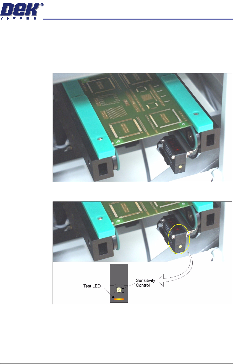
The board at left/right optos switching threshold can be adjusted by means of a
sensitivity control. This ensures that when a board is fed into the machine (via
the transport belts) the sensor output switches to ON.
To achieve an optimum setting carry out the following procedure:
1. Place a board on the rails covering the sensor.
2. Turn the sensitivity control fully anti-clockwise, ensure that the amber LED
is extinguished.
3. Re-adjust the sensitivity control clockwise until the amber LED illuminates.
NOTE
If the amber LED is flashing, this indicates a week signal. Re-adjust the
sensitivity control.
4. Remove the board from the rails and confirm the amber LED extinguishes.
TRANSPORT RAILS MODULE
ADJUSTMENTS AND SETTINGS
16.8 Technical Reference Manual Chapter Issue 4 Jan 10
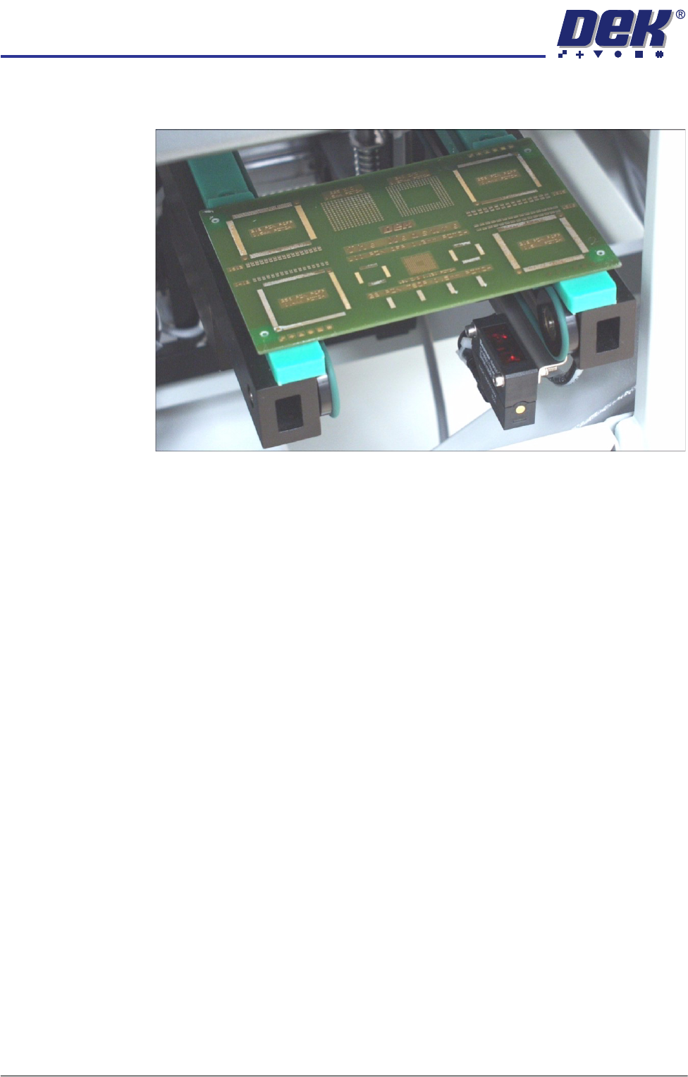
5. Turn the board 90° and position back onto the rail system, (so that the board
lies on top of the rail system as shown in the figure below).
6. Confirm that the amber LED is extinguished. If the amber LED illuminates,
turn the sensitivity control anti-clockwise until the amber LED extinguishes.
7. Remove the board.
8. Position the board back on the rail system, as in Step 1, and confirm that the
amber LED illuminates.
9. If the board has holes or cut-outs, go to Step 11.
10. Go to Step 14.
11. Slide the board backward and forward across the sensor ensuring that the
LED is only triggered by the leading and trailing edges of the board.
12. If the LED flickers when encountering holes or cut-outs, turn the sensitivity
control clockwise a further quarter turn.
13. Repeat Steps 11 and 12 until the correct setting is achieved.
14. Remove the board from the rails and confirm that the amber LED extin-
guishes.