Transport Rails Module.pdf - 第8页
TRANSPORT RAILS MODULE ADJUSTMENTS AND SETTINGS 16.8 Technical Re ference Manual Chapter Issue 4 Jan 10 5. T u rn the board 90° and position back onto the rail system, (so that the board lies on top of the rail system as…
TRANSPORT RAILS MODULE
ADJUSTMENTS AND SETTINGS
Chapter Issue 4 Jan 10 Technical Reference Manual 16.7
Board at Left/
Right Optos
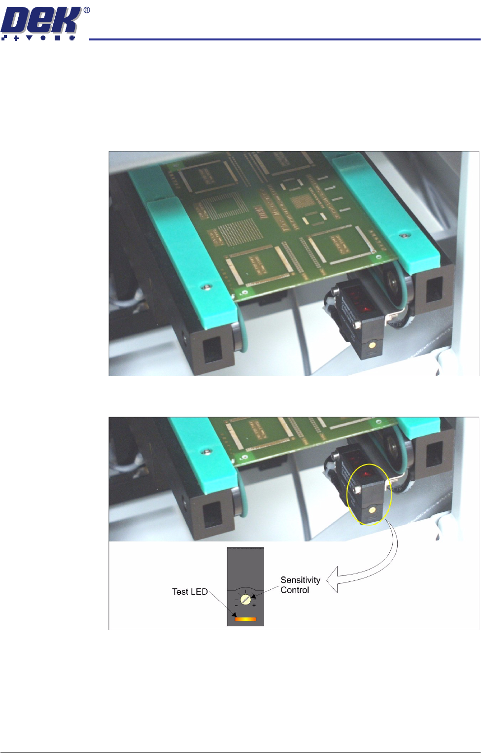
The board at left/right optos switching threshold can be adjusted by means of a
sensitivity control. This ensures that when a board is fed into the machine (via
the transport belts) the sensor output switches to ON.
To achieve an optimum setting carry out the following procedure:
1. Place a board on the rails covering the sensor.
2. Turn the sensitivity control fully anti-clockwise, ensure that the amber LED
is extinguished.
3. Re-adjust the sensitivity control clockwise until the amber LED illuminates.
NOTE
If the amber LED is flashing, this indicates a week signal. Re-adjust the
sensitivity control.
4. Remove the board from the rails and confirm the amber LED extinguishes.
TRANSPORT RAILS MODULE
ADJUSTMENTS AND SETTINGS
16.8 Technical Reference Manual Chapter Issue 4 Jan 10
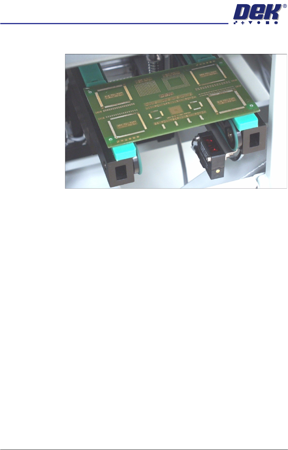
5. Turn the board 90° and position back onto the rail system, (so that the board
lies on top of the rail system as shown in the figure below).
6. Confirm that the amber LED is extinguished. If the amber LED illuminates,
turn the sensitivity control anti-clockwise until the amber LED extinguishes.
7. Remove the board.
8. Position the board back on the rail system, as in Step 1, and confirm that the
amber LED illuminates.
9. If the board has holes or cut-outs, go to Step 11.
10. Go to Step 14.
11. Slide the board backward and forward across the sensor ensuring that the
LED is only triggered by the leading and trailing edges of the board.
12. If the LED flickers when encountering holes or cut-outs, turn the sensitivity
control clockwise a further quarter turn.
13. Repeat Steps 11 and 12 until the correct setting is achieved.
14. Remove the board from the rails and confirm that the amber LED extin-
guishes.
TRANSPORT RAILS MODULE
ADJUSTMENTS AND SETTINGS
Chapter Issue 4 Jan 10 Technical Reference Manual 16.9
Front Rail Parallelism
WARNING
BOARD CLAMPS. EXTREME CARE MUST BE EXERCISED WHEN WORKING IN
THE TOOLING AREA OF THE MACHINE TO AVOID INJURY. THE FOILS ON THE
FRONT AND REAR BOARD CLAMPS ARE VERY SHARP.
NOTE
The Front Rail Parallelism is factory set and shouldn’t normally need to be
adjusted.
1. Select Open Cover Commands.
2. Select Carriage To Rear.
3. Select Unload Screen.
4. Open the front printhead cover.
5. Remove the screen from the machine.
6. Close the front printhead cover.
7. Press the System button.
8. Select Back.
9. Select Maintenance.
10. Select Diagnostics.
11. Use Next or Previous to highlight Rail System.
12. Select Select Module.
13. Ensure that Home Rail Width is highlighted.
14. Select Run Diagnost.
15. Select Exit.
16. Use Next or Previous to highlight Rising Table.
17. Select Select Module.
18. Use Next or Previous to highlight Raise Table to Vision Height.
19. Select Run Diagnost.
20. Select Exit.
21. Use Next or Previous to highlight Rail System.
22. Select Select Module. The board clamps are released.
23. Open the front printhead cover.
24. Remove any tooling from the manual tooling plate.
25. Remove the board clamp from the front transport rail, Board Clamp
Replacement - Replacement Procedures section of this chapter refers.
26. There are two versions of the rail setting jig (DEK Part No. 191156) and they
are labelled:
• Standard Rails (round belts)
• Heavy Board Rails (flat belts)