YSM40 Mainte_E.pdf - 第114页
3-46 3 Periodic maintenance items 5.2.4 Cleaning the switching valve gasket Cleantheswitc hingvalv egasketonceayearevenw henthiscleaningintervalmayv arydependingonthe supplyairstatusoroperatingtime…
3-45
3
Periodic maintenance items
5.2.3 Cleaning and lubricating the clutch and hook
Asageneralguide,theclutchshouldbecleanedandlubricatedonceperyear,althoughthismayvary
somewhatdependingontheairsupplyconditionsandtheoperatingtime.
1
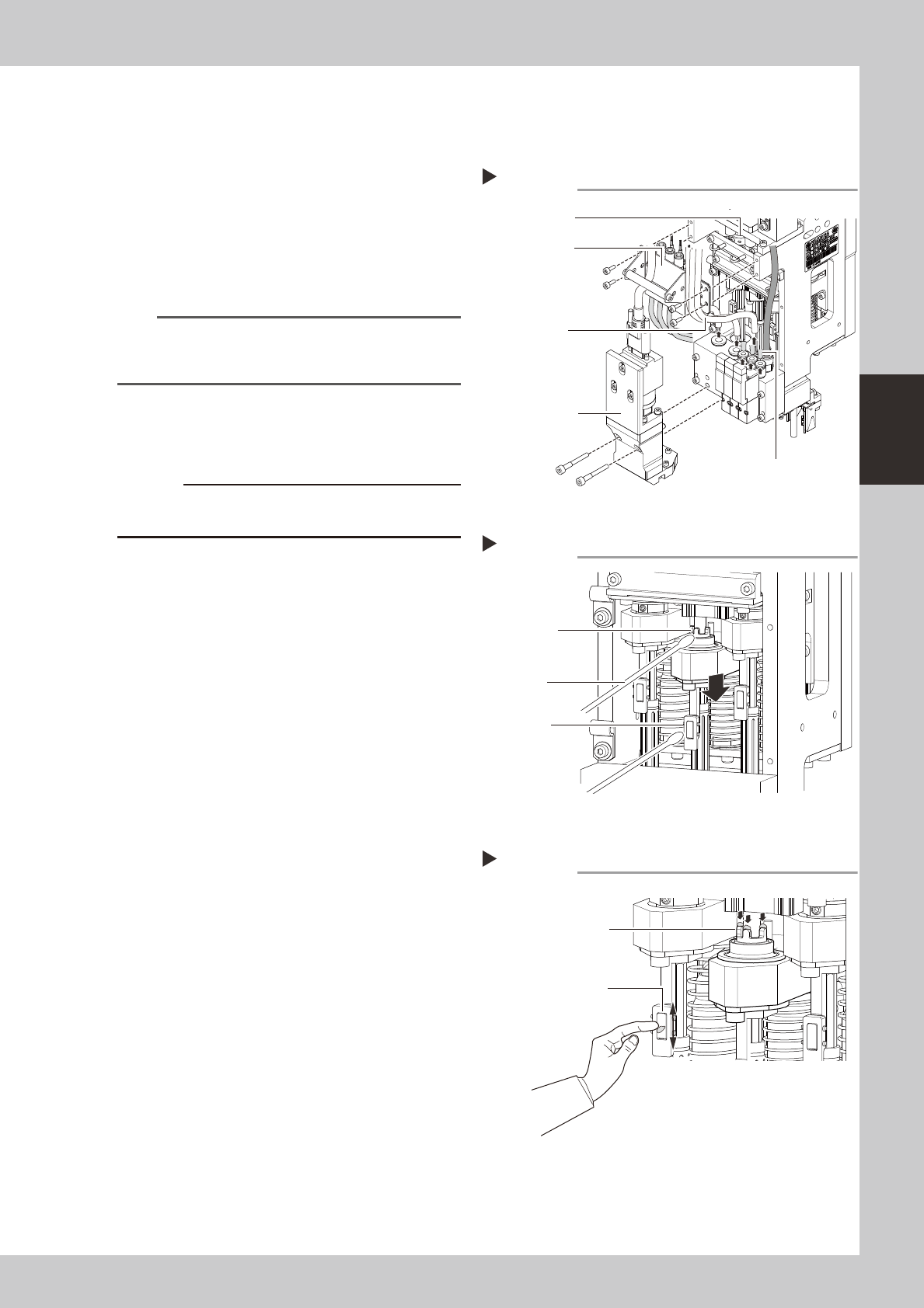
Remove the air hoses, etc.
1 Disconnect three air hoses (transparent)
and three air hoses (yellow).
2. Use a hex wrench to loosen and remove
the four bolts holding the bracket.
533G2-N5-00
n
NOTE
If it is difficult to get access to the clutch and hook,
remove the side-view camera. (Remove the mounting
bolts (2 pcs.).)
2
Remove the rotary unit.
See 2.1“Cleaning the rotary unit” to remove
the rotary unit.
c
Put a mark on the removed rotary unit so that you can
easily return it in the original position after cleaning.
3
Clean the clutch and hook.
Clutch
Lower the clutch and wipe off the grease
and contaminant from the clutch with a
cotton swab.
Hook
Wipe off the grease and contaminant from
the hook with a cotton swab.
533A6-N5-10
4
Lubricate the clutch and hook.
Clutch
Use your fingertip to apply the specified
grease (LG2) to the clutch threads.
Hook
Use your fingertip to fill the clearances with
the grease by rubbing it against the front of
the hook.
533A7-N5-10
5
Wipe off the excess grease.
Clutch
1. Turn the clutch on and off a few times.
2. Use a cotton swab to wipe off the excess
grease that has collected in the clutch’s
valleys and also came out of the clutch.
Hook
Wipe off the excess grease with a cotton
swab.
6
Reinstall the rotary unit.
See 2.1 “Cleaning the rotary unit” to reinstall
the rotary unit.
Step 3
Scissors gear
Pinion gear
Cotton swab
Cleaning the clutch and hook
Lubricating the clutch and hook
Step 4
Apply the grease to the
threads.
Use your fingertip to fill
the clearances with the grease
by rubbing it against the front
of the hook.
Step 1
Removing the air hoses, etc.
Bracket
Scissors gear
Side-view camera
Air hoses
(yellow)
Air hoses
(transparent)
3-46
3
Periodic maintenance items
5.2.4 Cleaning the switching valve gasket
Cleantheswitchingvalvegasketonceayearevenwhenthiscleaningintervalmayvarydependingonthe
supplyairstatusoroperatingtime.
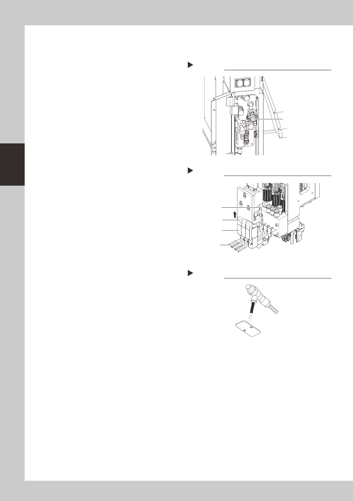
1
Turn off the supply air and power
to the machine.
1. Exit the software and turn off the power
switch on the machine.
2. Turn the "air supply/exhaust switch" inside
the panel at the lower left portion of the
machine rear clockwise to stop the air
supply.
533F8-N5-00
2
Disconnect the switching valve
connectors.
Disconnect the connectors that are
connected to the top of the switching valve.
533F7-N5-00
3
Remove the switching valve.
Use a Phillips precision screwdriver to loosen
the mounting bolts (2 pcs.) and remove the
switching valve.
4
Clean the gasket.
Blow the air to clean the gasket.
533F9-N5-00
5
Install the switching valve at its
original position in the reverse
order of the steps described above.
Connect also the connectors to their original
positions.
Removing the switching valve
Step 2,3
Switching valve
Connector
Mounting bolt
Gasket
Stopping the air supply
Step 1
Air supply/exhaust switch
Cleaning the gasket
Step 4
Gasket
Air blow tool
3-47
3
Periodic maintenance items
5.3 FL head
5.3.1 Cleaning the spline shaft
Adheredforeignmatterandsoilinginsidethesplineshaft'sairpassagescancausepickupandplacement
errors.Topreventthis,thespineshaftinteriorshouldbecleanedonceperyear(generalguideline),although
thismayvarysomewhatdependingonthesuppliedairconditionandtheoperatingtime.
1
Remove the nozzle from the head.
Either remove the nozzles by hand, or place
all nozzles in the nozzle station.
2
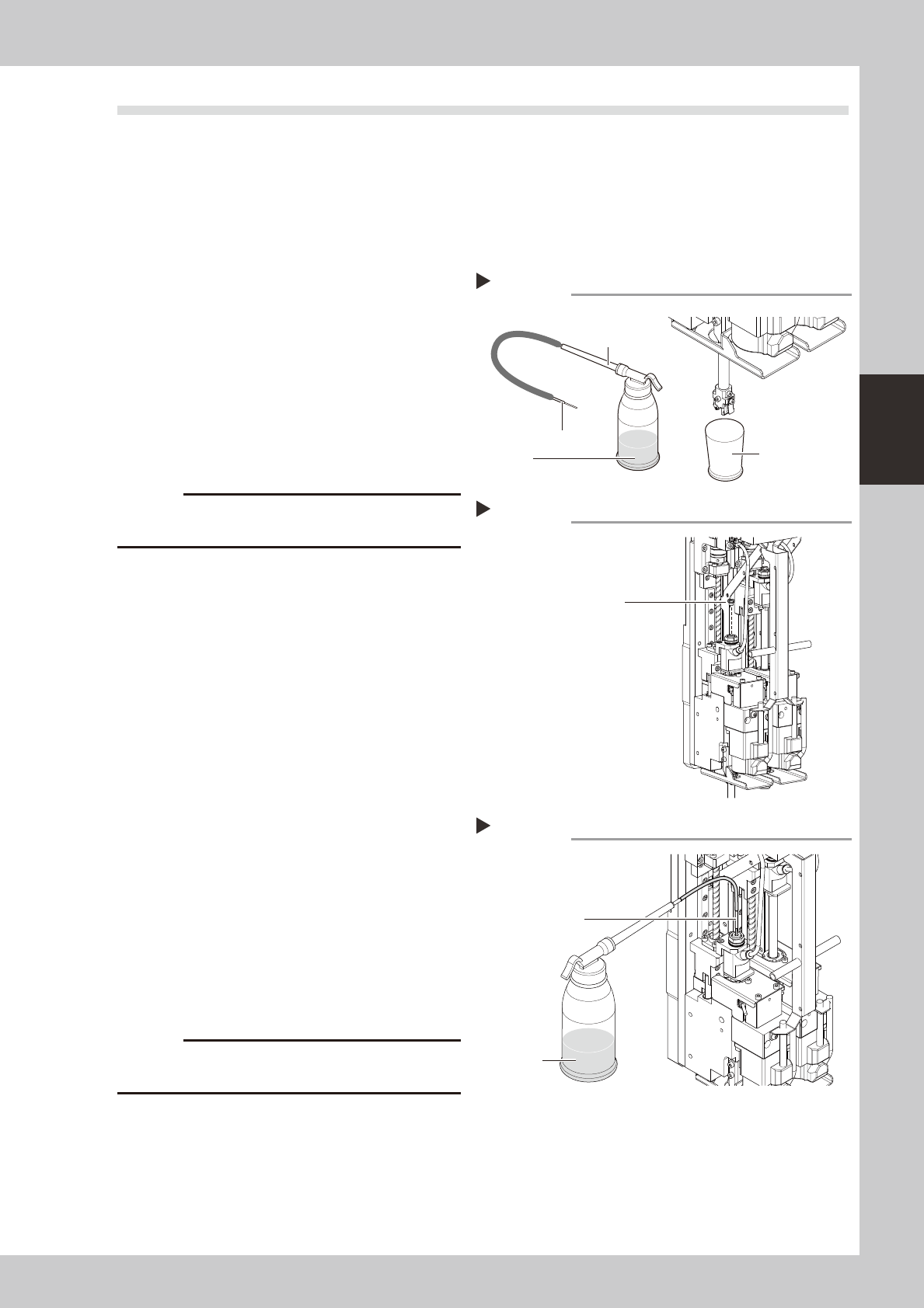
Prepare the cleaning kit (KHN-
M8860-00X).
1. Pour IPA (isopropyl alcohol) into the
container of the cleaning kit.
2. Spread a cloth directly below the
working position, or place a paper cup,
etc., there.
533A8-N5-00
c
3
Remove the maintenance bolt.
Use a slotted screwdriver to remove the
maintenance bolt shown in the figure at
right.
533A9-N5-00
4
Clean the inside of the spline shaft.
1. Insert the nozzle of the cleaning kit into
the cleaning hole of the spline shaft.
2. Pour alcohol (IPA) into the spline shaft air
path to clean away dust and grime.
533B1-N5-00
5
Blow air into the spline air path.
1. Connect an air blow tool (optional
purchase item) to the air joint.
2. Place a cloth against the end of the
spline shaft, then air-blow the spline shaft
interior with the air blow tool.
3. When the cloth placed against the spline
shaft end is no longer being soiled by the
exiting air, screw the maintenance bolt in
again.
c
to wear safety goggles.
6
Clean the spline shaft of the other
head.
Repeat steps 3 to 5 to clean the inside of
the spline shaft of the other head.
7
Reattach the nozzle.
Cleaning
Step 2
Pump
Nozzle
Rug or paper cup
IPA
Maintenance bolt
Step 3
Maintenance bolt
Cleaning the spline
Step 4
Nozzle
IPA