YSM40 Mainte_E.pdf - 第123页
3-55 3 Periodic maintenance items 5.7 Controller 5.7.1 Cleaning the filter T here are 2 filter types that require cleaning, and they are located at the following 3 positions: System controller filter : 1 filter at rear c…
3-54
3
Periodic maintenance items
5.6 PU axis
5.6.1 Cleaning and lubricating the PU axis ball screw
1
Make the preparation for cleaning.
e
1. Remove all items that are affected by
magnetism, such as a watch and ID
card.
2. Press the emergency stop button.
3. Lower the feeder exchange carriage by
using the clamp switch and remove the
feeder exchange carriage.
2
Set the Lane 1 conveyor to its
maximum width.
1. Press the [Device] button to perform axis
movement and set the Lane 1 conveyor
to its maximum width.
2. Lower the push-up plate.
3
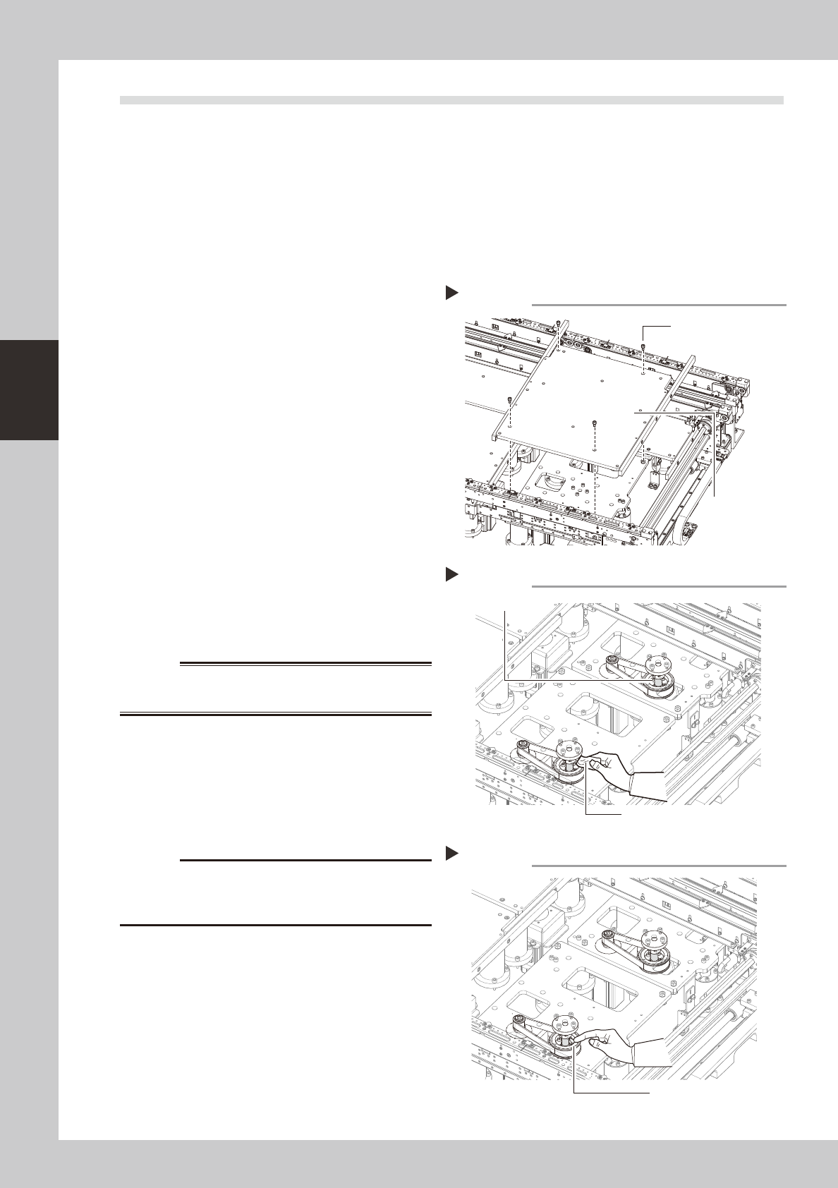
Remove the push-up plates (at
Lanes 1 & 2).
e
1. Press the [Emergency Stop] button.
2. Use a hexagon wrench (4) to remove the
4 bolts which secure the push-up plate,
then remove the push-up plate.
3. Release the Emergency Stop status, then
press the [Device] button to perform axis
movement which raises the PU axis to its
maximum height.
53350-N5-00
w
WARNING
4
Clean the ball screw.
e
1. Press the [Emergency Stop] button.
2. Using a cloth, etc., which produces no
lint, clean the entire ball screw, wiping
off all soiling and old grease.
53355-N5-00
c
Carefully wipe the lead grooves of the ball screw during
is not produced.
5
Apply grease.
Apply the specified grease (NSL) by hand
uniformly over the surface and lead grooves
of the ball screw.
53356-N5-00
6
Remount the push-up plate.
e
Cancel emergency stop and lower the push-
up unit. Then press the emergency stop
again and reinstall the push-up plate.
Removing the push-up plate
Step 3
Push-up plate securing
bolts (4 bolts)
Push-up plate
Cleaning the ball screw
Step 4
Cleaning cloth
Ball screw
Applying grease
Step 5
Grease
3-55
3
Periodic maintenance items
5.7 Controller
5.7.1 Cleaning the filter
There are 2 filter types that require cleaning, and they are located at the following 3 positions:
System controller filter : 1 filter at rear center of machine.
Servo controller filters
: 2 filters, 1 at the front right side, and 1 at the right side as viewed when facing the machine's rear.
1
Detach the batch change carriage.
Detach the batch change carriage, and
turn the machine power OFF to ensure
safety.
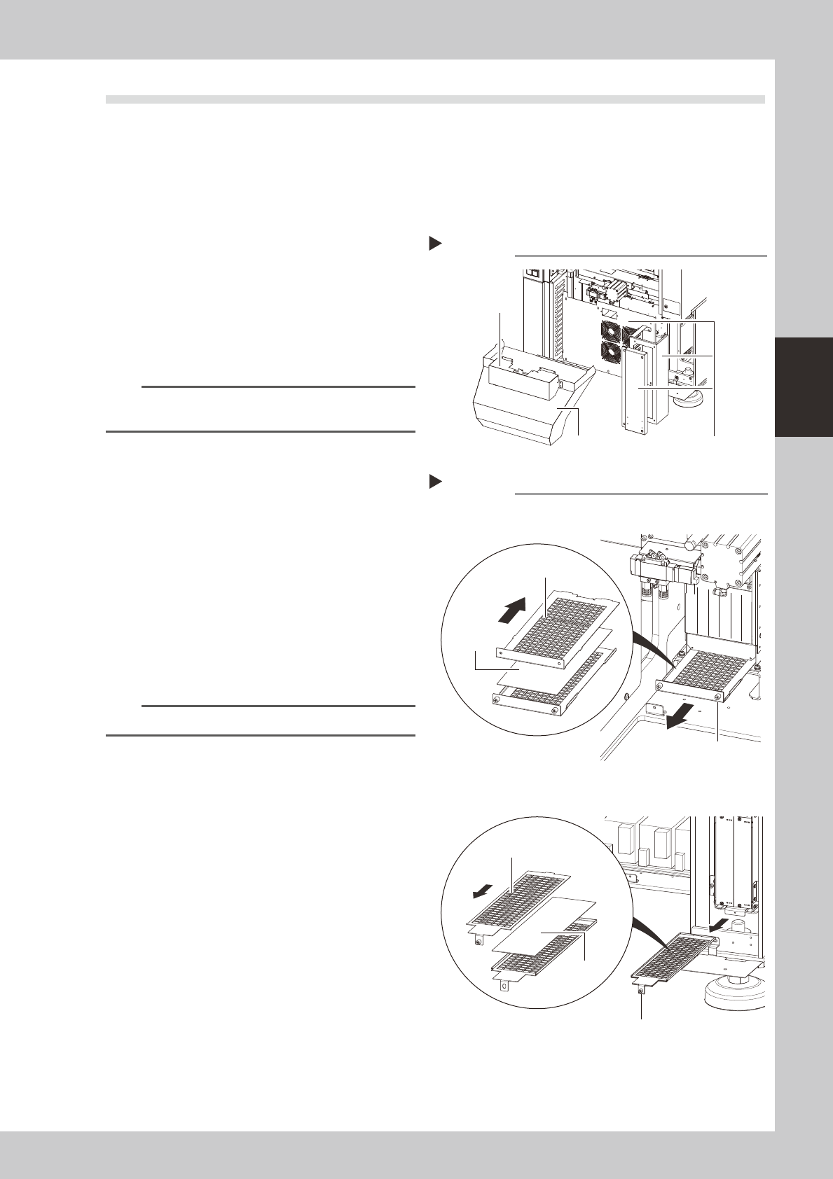
2
Remove the front cover and duct.
Remove the front cover and duct as
described in Chapter 1, section "2.1
Removing the tape cutter duct".
n
NOTE
The figure at right shows the rear side. There is no need
to remove the front-side cover and duct.
3
Remove the covers.
As shown in the figure at right, remove the
rear center cover and the right-side cover.
53370-N5-00
4
Remove the filter.
Use a Phillips screwdriver to loosen the
screws which secure the filter, then extract
the filter.
53371-N5-00
5
Clean the filter.
Use a vacuum cleaner or vacuum tool to
remove the dust sticking to the filter.
n
NOTE
If a filter replacement is not required, proceed to Step 7.
6
Replace the filter.
If the filter is too soiled to be cleaned by
air-blowing, or if it is in a degraded
condition, replace it with new one as shown
in the figure at right.
7
Reinstall the filter.
Reinstall the filter by reversing its removal
procedure.
8
Reattach the covers.
Removing the cover (machine rear)
Step 2, 3
Remove these 3 coversDuct
Front cover
Removing the filter
System controller
Servo controller
Step 4
Slide the top side
toward the front
Filter
Slide the top side
toward the rear
Filter securing screw
Filter securing screw
Filter
3-56
3
Periodic maintenance items
5.8 Air / mist filter
5.8.1 Cleaning the filter and cup
Airfiltersandoilmistfiltersareinstalledtopreventoil,water,andimpurities,etc.,frombeingintroducedinto
themachinefromtheaircompressor.Theproceduresforinspecting,cleaning,andreplacingthesefiltersare
givenbelow.
c
decoupled.
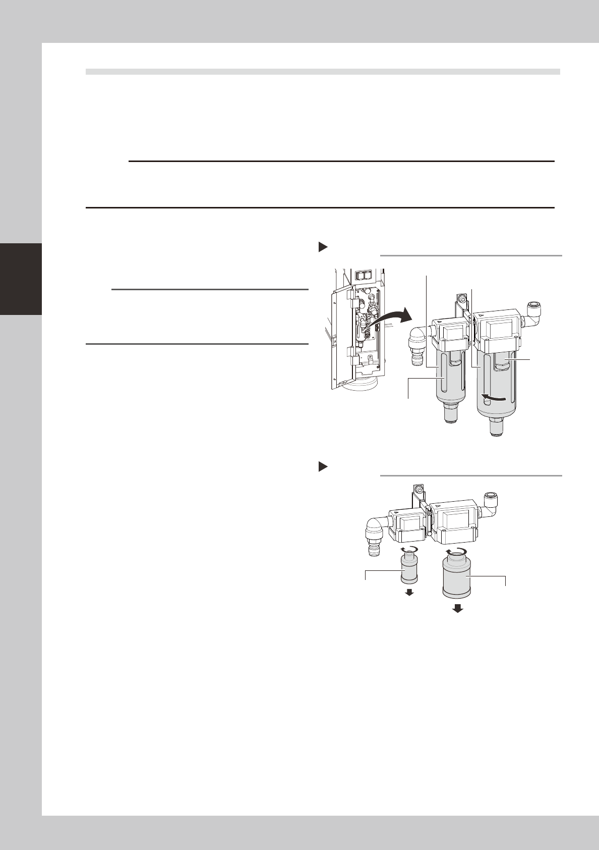
1
Check the inside of the filer cup.
Check for oil or water deposits in the filter
cup through the window. If the window is
dirty, follow the steps below to clean the
filter cup.
TIP
The drain cock at the bottom of the filter cup is an
auto-drain type. It automatically drains the oil or water
when deposited in the cup. We recommend
connecting a hose to this drain cock.
2
Remove the filter cup.
While pressing the cup's button, rotate the
cup in the direction shown at right, then pull
downward to remove the cup. The removed
cup has a double construction. Only the
transparent inner cup requires cleaning.
53372-N5-00
3
Clean the inside of the filter cup.
1. Lightly clean the filter cup with water.
2. Then, pour water-diluted neutral
detergent into the filter cup and clean
the inside while shaking it.
3. Air blow the filter cup and wipe away
any moisture with clean cloth or paper.
53373-N5-00
4
Check the filter media status.
Rotate the media to remove it, and check it
for soiling and clogging. If soiled, replace it
with a new media indicated in the
Consumable Parts List.
5
Install the media and cup.
Install the media and cup by reversing the
removal procedure given above.
6
Reconnect the air hose to the air
coupler.
After connecting the air hose, check that no
air is leaking.
Removing the cup
Step 2
Filter cup (inner)
Air filter
Oil mist filter
Button
Removing and checking the filter media
Step 4
Mist filter
Air filter