YSM40 Mainte_E.pdf - 第135页
4-10 4 Long-term inspection and other maintenance 4.2 Removing the par ts subject to wear 4.2.1 Removing the head cover and cylinder 1 Remo ve the panel. Use a Phillips screwdriver to remove t he screws that secure the p…
4-9
4
Long-term inspection and other maintenance
4.1 Removing the pumps and making preparations
Checksafetyagainbeforeremovingthepumps.
Read“Precautionswhencleaningthepumpandreplacingthepartssubjecttowear”ontheprecedingpageandfollow
theinstructionstoensurethesafety.
1
Remove the tape cutter duct.
See 2.1 “Removing the tape cutter duct” in
Chapter 1 for instructions on how to remove
the tape cutter duct.
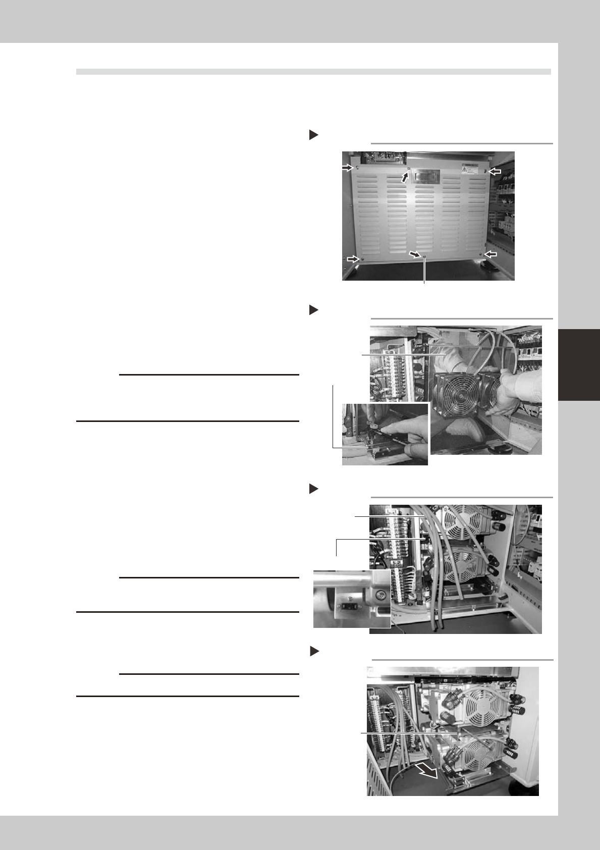
2
Remove the main unit cover.
1. Use a Phillips screwdriver to loosen the
mounting screws (6 pieces) shown in the
photo at right, then remove the main unit
cover.
2. Disconnect the ground wire located
behind the cover.
53436-N5-00
3
Remove the pump cover.
Use a short screwdriver or ratchet wrench to
remove the mounting screws (6 pieces),
then remove the pump cover.
53437-N5-00
c
damage the transformer harness wire located next to
the pump.
4
Remove the air hoses.
In the case of a 4-beam machine, remove 4
air hoses each on the left and right sides. In
the case of a 2-beam machine, remove only
4 air hoses on the right side as viewed from
the front.
53438-N5-00
5
Remove the upper pump.
1. Disconnect the power connector and
ground wire from the side housing.
c
lose the washer.
2. Use a hex wrench (4) to remove the four
bolts that secure the upper pump.
3. Pull out the upper pump to the front side.
c
6
Remove the lower pump.
1. Use a hex wrench (4) to remove the two
bolts (front side) that secure the lower
pump.
2. Remove the lower pump, and also
disconnect the power connector and
ground wire from the side housing.
53439-N5-00
Removing the main unit cover
Step 2
Mounting screw
Removing the pump cover
Step 3
Mounting screw
Pump cover
Disconnecting the air hoses and power connector
Step 4, 5
Air hose
Power connector
Removing the pump
Step 5, 6
Mounting bolts
(4 places)
4-10
4
Long-term inspection and other maintenance
4.2 Removing the parts subject to wear
4.2.1 Removing the head cover and cylinder
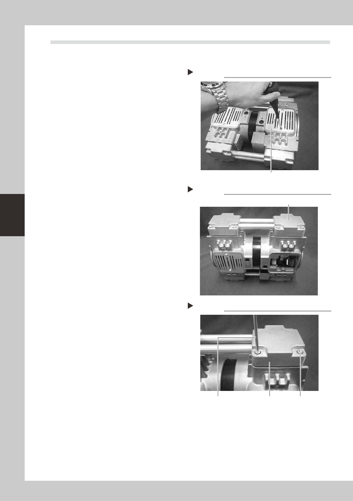
1
Remove the panel.
Use a Phillips screwdriver to remove the
screws that secure the panel.
53421-N5-00
2
Place the pump upright.
Place the pump in an upright position so
that the head whose parts are to be
replaced is at the top.
53422-N5-00
3
Remove the mounting bolts.
Use a hex wrench to remove the four bolts
(M6×L30) each securing the left and right
head covers (remove a total of 8 bolts).
4
Remove the head covers.
Remove the head covers along with the
connecting pipe.
53423-N5-00
Removing the panel
Step 1
Panel
Placing the pump upright
Step 2
Head whose parts are to be replaced
Removing the head cover
Step 3, 4
Hex wrench Head cover Mounting bolt
4-11
4
Long-term inspection and other maintenance
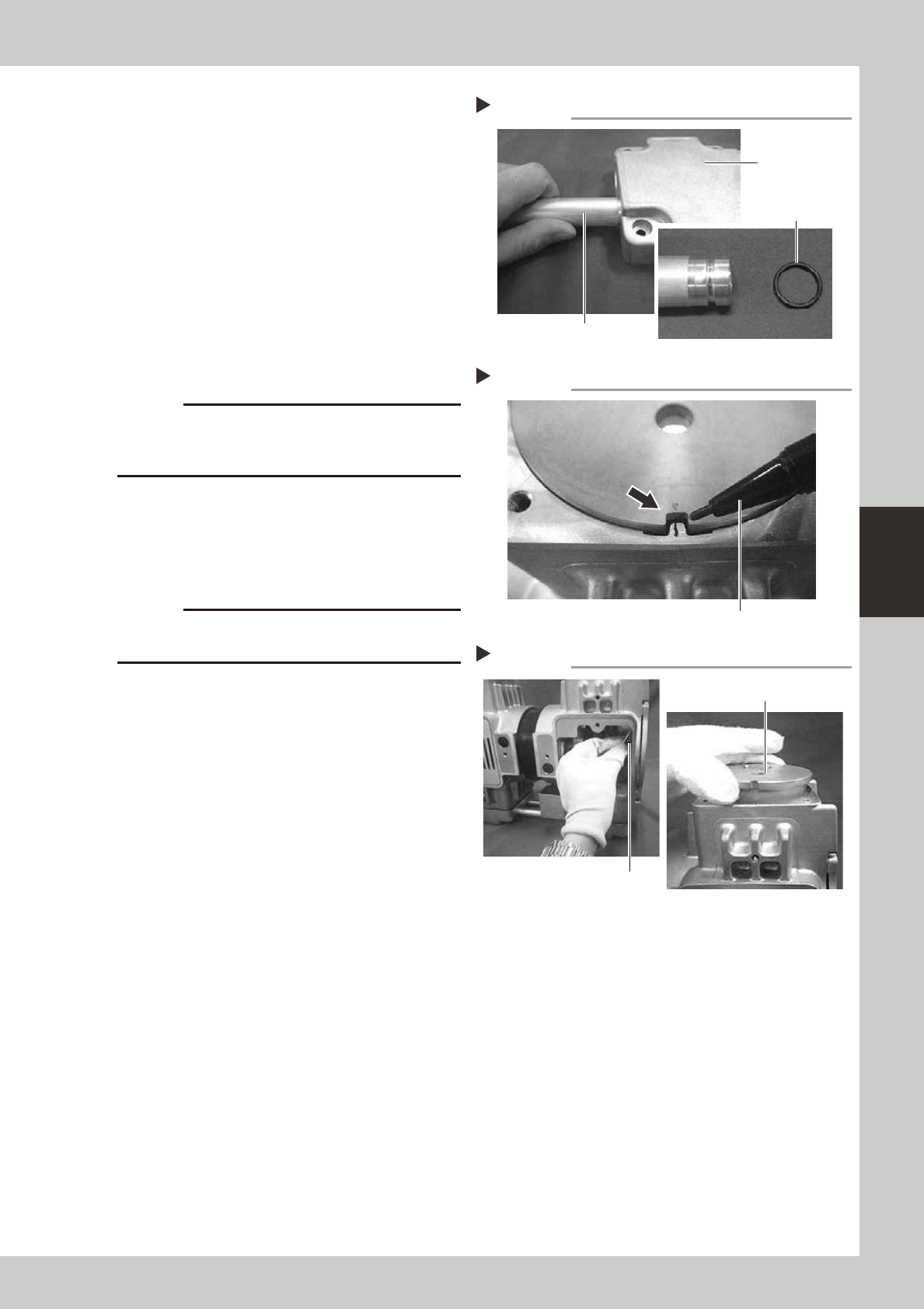
5
Replace the O-rings.
1. Remove the connecting pipe from the
head covers.
2. Replace the O-rings (4 pieces) on the
connecting pipe with new ones. At this
point, apply grease to the entire surface
of each new O-ring.
53424-N5-00
6
Put a mark.
Before removing the cylinder, put a mark on
the casing and cylinder with an oil-based
marker pen to indicate the reassembly
position.
53425-N5-00
c
The pump will break down if the cylinder is reassembled
the reassembly position.
7
Raise the cylinder.
Wear gloves and slowly turn the fan upward
to raise the cylinder.
8
Remove the cylinder.
c
of the cylinder installation surface.
53426-N5-00
Replacing the O-ring
Step 5
Connecting pipe
Head cover
O-ring
Marking
Step 6
Oil-based marker pen
Removing the cylinder
Step 7, 8
Cylinder
Fan