YSM40 Mainte_E.pdf - 第155页
A-1 Appendix 1. Specifications 1.1 Air regulator unit T heairregulatorforcontrollingtheairpressuretothemachine'spneumaticunitsislocatedatthelowerleft panelontherearsideofthemachine.Specify…

A-1
Appendix
1. Specifications
1.1 Air regulator unit
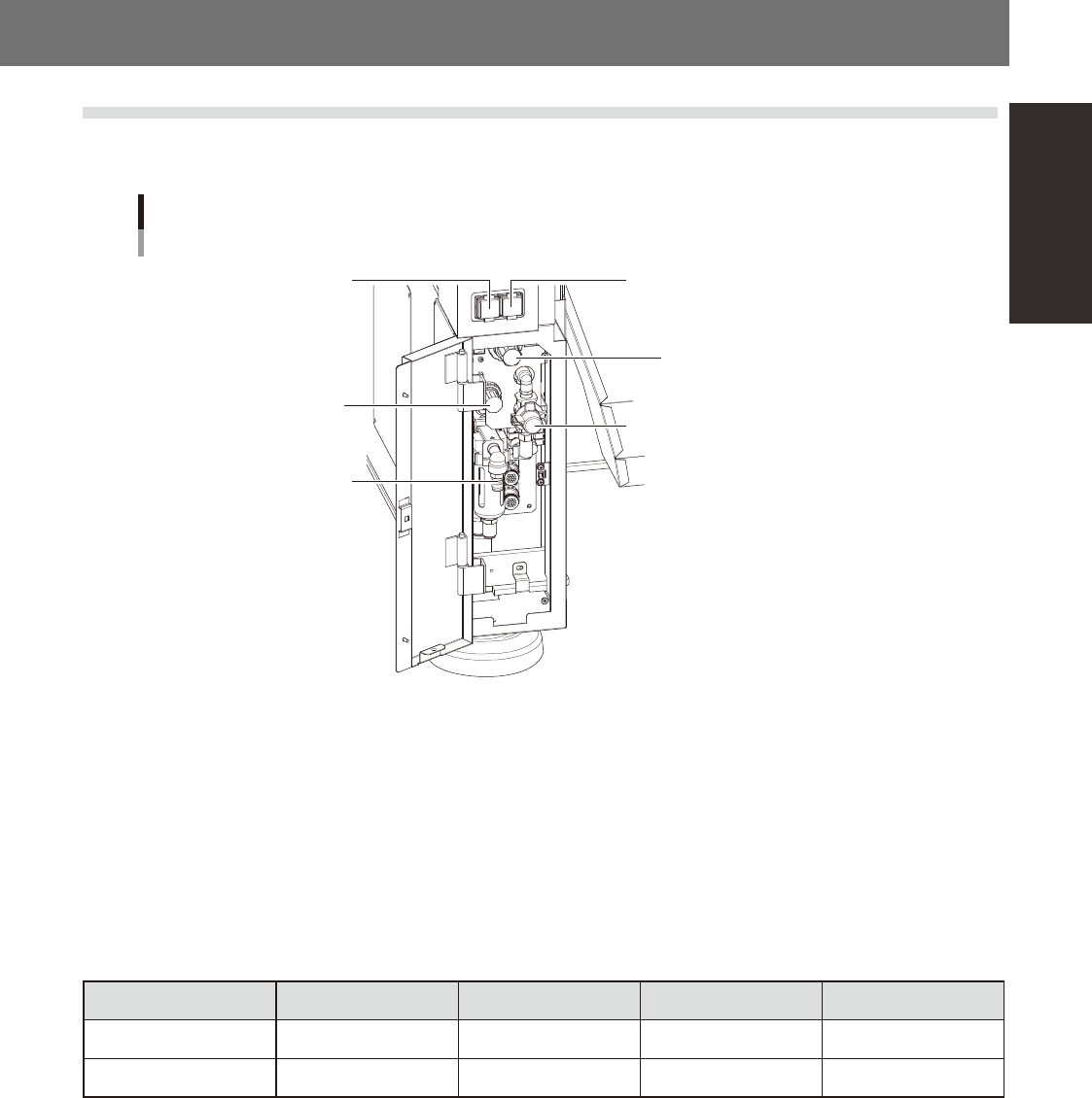
Theairregulatorforcontrollingtheairpressuretothemachine'spneumaticunitsislocatedatthelowerleft
panelontherearsideofthemachine.Specifytheappropriateairpressuresettingshownbelow.
Air pressure regulator and pressure gauge
Setting air pressure gauge
[PNEUMATIC]
Setting air pressure regulator
[PNEUMATIC]
Air supply/exhaust switch
Head air pressure gauge
[HEAD BLOW]
Head air pressure regulator
[HEAD BLOW]
Source air connector
53A01-N5-00
n
Supply air pressure
Thisisthepressureofthesourceairsuppliedtothemachine.Beforesettingtheairpressurewiththeairregulator,make
surethatthissupplyairpressureisinthefollowingoptimalrange.
YSM40:0.45MPato0.70MPa
n
Air pressure gauge (display)
Whenwithinthenormalrange,theairpressuredisplaysingreen.Whentheairpressureisbeyondtheupper/lowerlimit
values(airdowndetection),anerroroccurs,andtheairpressuredisplaysinred.
n
Air pressure setting values and upper/lower limit values
Head Setting Value Lower Limit Value Upper Limit Value
Setting air pressure Common 0.40Mpa (±0.01) 0.39Mpa 0.41Mpa
Head air pressure Common 0.040Mpa (±0.001) 0.039Mpa 0.041Mpa
n
Air supply/shutoff switch (valve)
Turningthisswitchtotherightshutsoffairsupplyandexhaustsairthatremainsinsidethemachine.
n
Source air connector
Prepareanairhosewithaninnerdiameterofatleast8mmhavinga40SHsocket(NittoKoki,orequivalent),andconnect
ittothisconnector.Usedry,cleanairpassedthroughanairfilter.
A-2
Appendix
1.2 Power connection terminals
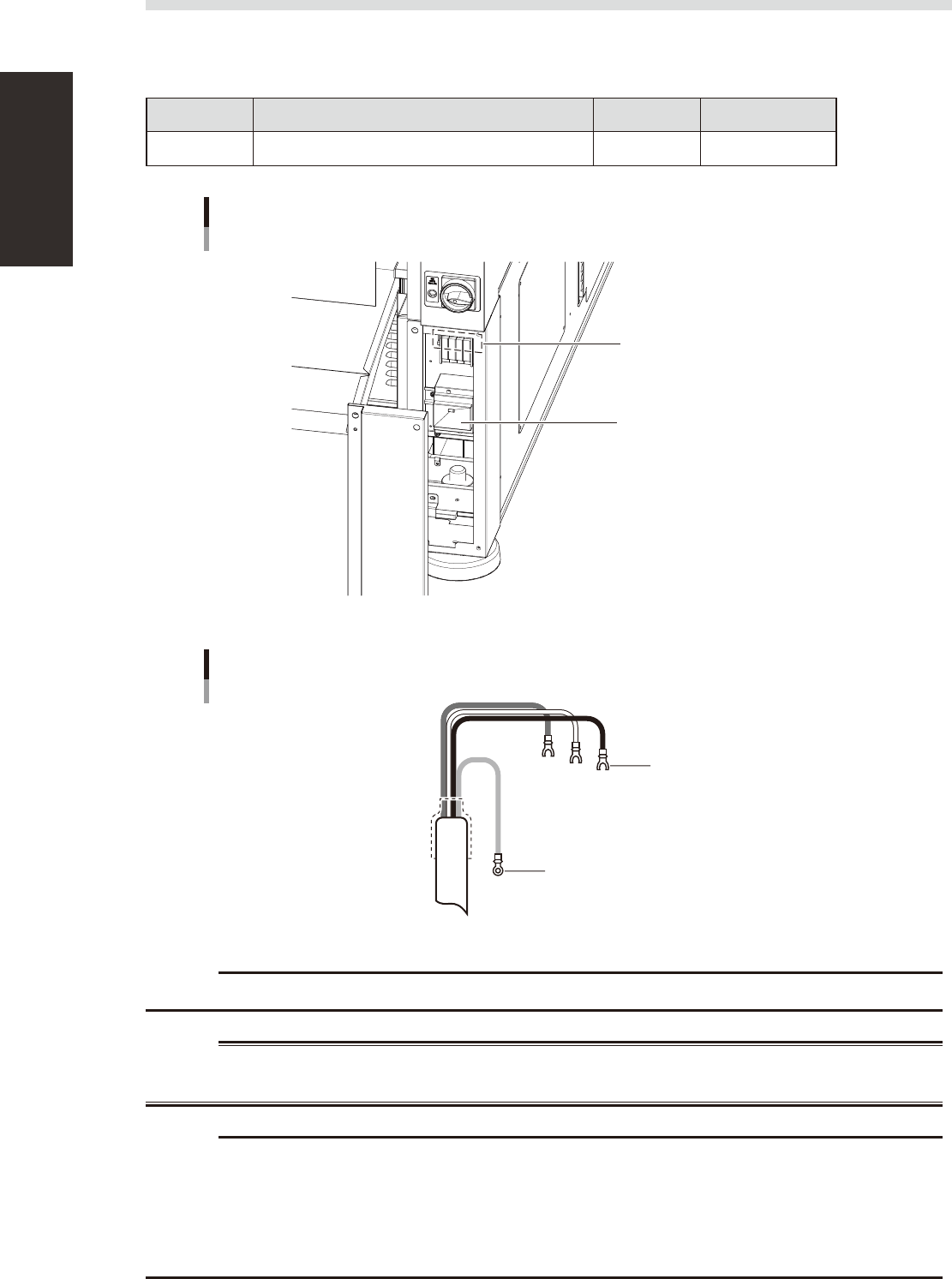
Thepowerconnectionterminalsarelocatedinsidethelowerrightpanelonthefrontofthemachine.Connect
thepowercableleadsasshownbelowtotheL1,L2,L3andgroundterminal(PE)onthepowerterminalblock.
n
Power supply specifications
Model name Power Frequency Power capacity
YSM40 3-phase AC 200/208/220/240/380/400/416V (±10%) 50/60Hz 13.9kVA
Power input terminals
(L1, L2, L3) and ground terminal
Main breaker
Power connection terminals
53A02-N5-10
Ring-tongue crimp terminal
Insulated crimp terminal
Power cable
L2
L1
L3
PE
53A03-N5-00
c
Use a power cable whose conductor cross-section area is greater than 5.5mm
2
.
w
WARNING
c
power input terminal block so that they are in the normal phase. Incorrect connection may cause the vacuum pump
to turn in the wrong direction and drastically shorten the service life of the components in the vacuum pump.