YSM40 Mainte_E.pdf - 第156页
A-2 Appendix 1.2 Power connection terminals T hepowerconnectionterminalsarelocatedinsidethelowerrightpanelonthefrontofthemachine.Connect thepowercableleadsasshownbelo wtotheL1,L2,L3andgroun…
A-1
Appendix
1. Specifications
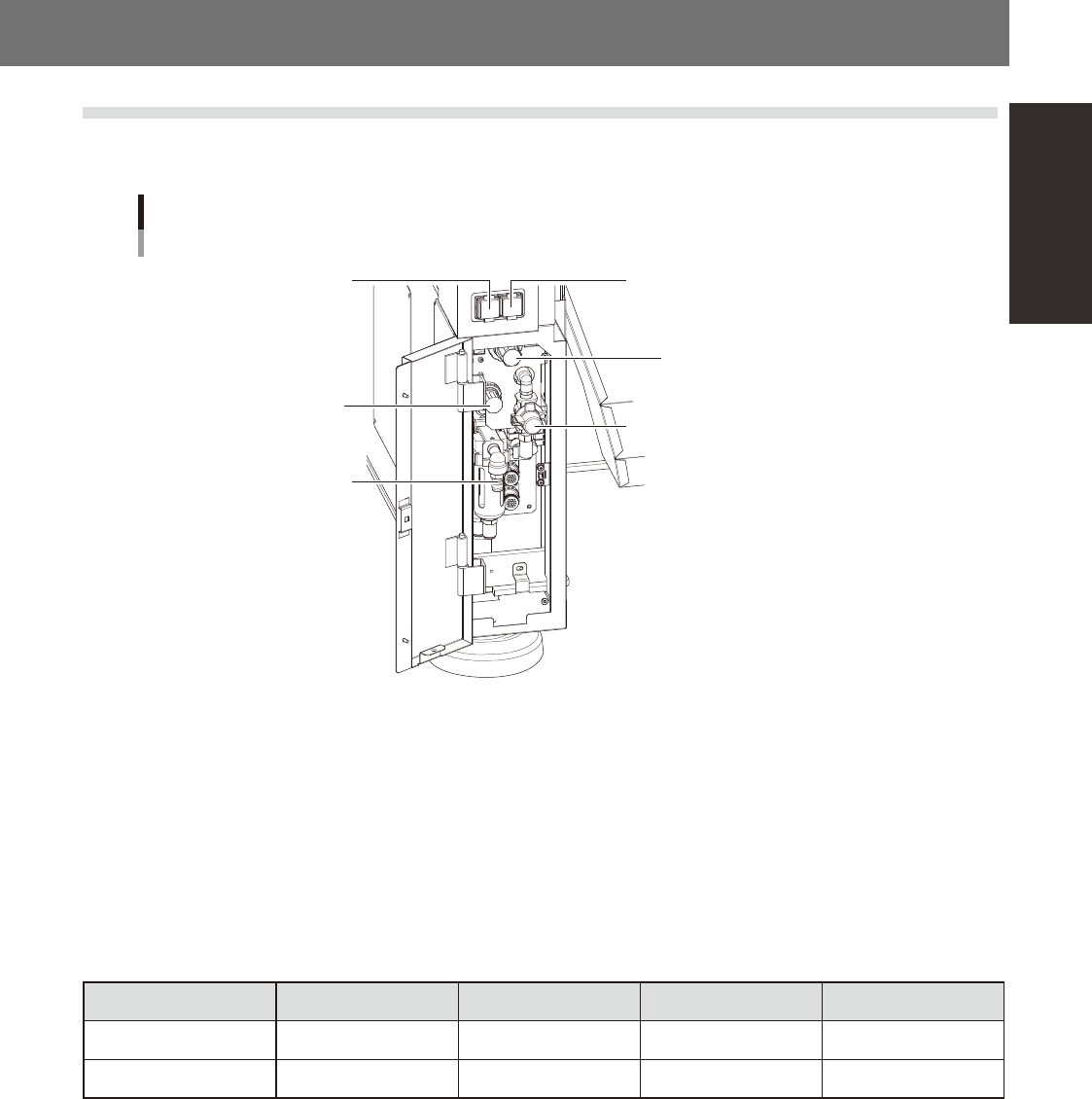
1.1 Air regulator unit
Theairregulatorforcontrollingtheairpressuretothemachine'spneumaticunitsislocatedatthelowerleft
panelontherearsideofthemachine.Specifytheappropriateairpressuresettingshownbelow.
Air pressure regulator and pressure gauge
Setting air pressure gauge
[PNEUMATIC]
Setting air pressure regulator
[PNEUMATIC]
Air supply/exhaust switch
Head air pressure gauge
[HEAD BLOW]
Head air pressure regulator
[HEAD BLOW]
Source air connector
53A01-N5-00
n
Supply air pressure
Thisisthepressureofthesourceairsuppliedtothemachine.Beforesettingtheairpressurewiththeairregulator,make
surethatthissupplyairpressureisinthefollowingoptimalrange.
YSM40:0.45MPato0.70MPa
n
Air pressure gauge (display)
Whenwithinthenormalrange,theairpressuredisplaysingreen.Whentheairpressureisbeyondtheupper/lowerlimit
values(airdowndetection),anerroroccurs,andtheairpressuredisplaysinred.
n
Air pressure setting values and upper/lower limit values
Head Setting Value Lower Limit Value Upper Limit Value
Setting air pressure Common 0.40Mpa (±0.01) 0.39Mpa 0.41Mpa
Head air pressure Common 0.040Mpa (±0.001) 0.039Mpa 0.041Mpa
n
Air supply/shutoff switch (valve)
Turningthisswitchtotherightshutsoffairsupplyandexhaustsairthatremainsinsidethemachine.
n
Source air connector
Prepareanairhosewithaninnerdiameterofatleast8mmhavinga40SHsocket(NittoKoki,orequivalent),andconnect
ittothisconnector.Usedry,cleanairpassedthroughanairfilter.
A-2
Appendix
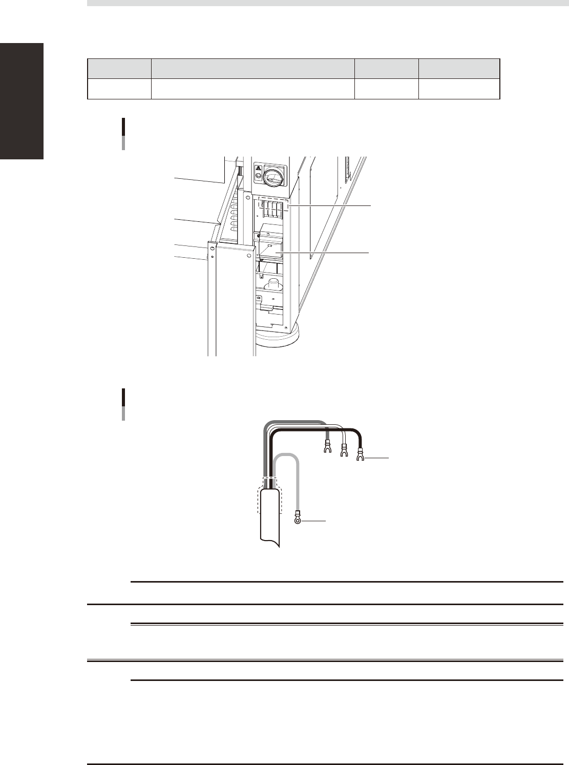
1.2 Power connection terminals
Thepowerconnectionterminalsarelocatedinsidethelowerrightpanelonthefrontofthemachine.Connect
thepowercableleadsasshownbelowtotheL1,L2,L3andgroundterminal(PE)onthepowerterminalblock.
n
Power supply specifications
Model name Power Frequency Power capacity
YSM40 3-phase AC 200/208/220/240/380/400/416V (±10%) 50/60Hz 13.9kVA
Power input terminals
(L1, L2, L3) and ground terminal
Main breaker
Power connection terminals
53A02-N5-10
Ring-tongue crimp terminal
Insulated crimp terminal
Power cable
L2
L1
L3
PE
53A03-N5-00
c
Use a power cable whose conductor cross-section area is greater than 5.5mm
2
.
w
WARNING
c
power input terminal block so that they are in the normal phase. Incorrect connection may cause the vacuum pump
to turn in the wrong direction and drastically shorten the service life of the components in the vacuum pump.
A-3
Appendix
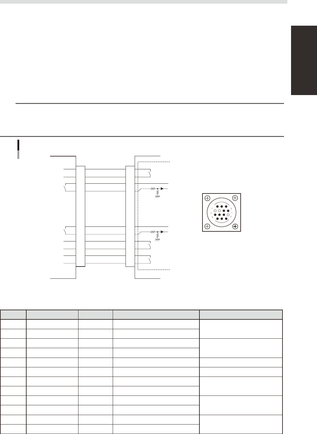
1.3 Connection between machines
Toexchangesignalssuchasboardrequestandoperationstatuswiththedownstreamorupstreammachine,the
"NEXTINTERFACE"and"PREVIOUSINTERFACE"connectorslocatedontherearofthemachineareused.The
"NEXTINTERFACE"connectorconnectstothedownstreammachine,andthe"PREVIOUSINTERFACE"
connectorconnectstotheupstreammachinesuchasaloader.
1.3.1 PREVIOUS INTERFACE connector
Whenthefollowingthreeconditionsaremet,thePREVIOUSINTERFACEcircuitinthemachineallowsthe
nextboardtobecarriedin.(ADVANCEDGATEisselected.)
1.Machineisreadyforcarryinginaboard(BUSYOUT:ON)
2.Boardcarry-insignalisinputfromtheupstreammachine.(BAIN[N0100421]:ON)
3.Automaticoperationsignalisinputfromtheupstreammachine.(URIN[N0100422]:ON)
n
NOTE
• When the automatic operation signal (UR IN) from the loader turns off during transfer of a board, the machine
temporarily stops carrying in the board.
• When the board being carried in is detected by the entrance sensor, the BUSY OUT signal turns off.
• Carrying in the board is nished when both the BUSY OUT and BA IN turn off.
1
2
3
4
5
6
7
8
9
10
11
12
13
14
7
12
4
8
1
14
11
3
BUSY OUT
(T01000E4)
+24V
+24V
LR OUT
(T01000E7)
UR IN
(N0100422)
BA IN
(N01000421)
Signal input during
board carry-in
Signal output to
request board carry-out
Signal output during
automatic operation
Signal input during
automatic operation
LE OUT
(T01000F3)
Signal input during
waiting for board
between machines
I/O BOARD
PREVIOUS INTERFACE circuit
This machine PREVIOUS INTERFACEUpstream
PREVIOUS INTERFACE
connector
AMP 206043-1
(14-pin receptacle)
53A04-N5-00
n
Board transfer signal specifications
PREVIOUSINTERFACE
Pin No. Signal name Address I/O specifications Signal specifications
1 BUSY OUT T01000E4 Relay contact (zero voltage) output
Signal output during board carry-in
2 BUSY OUT T01000E4 Relay contact (zero voltage) output
3 +24V Input common (+24V)
Signal input of board carry-out
request
4 BA IN N0100421 Voltage input
5 NC (with dummy pins) (Prevents misinsertion.)
6 to 8 NC
9 +24V Input common (+24V)
Signal input during automatic
operation
10 UR IN N0100422 Voltage input
11 LR OUT T01000E7 Relay contact (zero voltage) output
Signal output during automatic
operation
12 LR OUT T01000E7 Relay contact (zero voltage) output
13 LE OUT T01000F3 No-voltage output
Signal output during waiting for
board between machines
14 LE OUT T01000F3 No-voltage output