YSM40 Mainte_E.pdf - 第59页
2-1 2 Daily maintenance items Before beginning work In most cases, maintenance should be perfor med with the main power turned off. However , some maintenance tasks are perfor med under emergency stop conditions with the…

Chapter 2 Daily maintenance items
Contents
1
1
How to use the nozzle lubrication tool 2-3
1. Checking the nozzle 2-4
1.1 Check with software 2-4
1.1.1 Vacuum level when nozzle is open 2-6
1.2 Checking the nozzles visually 2-7
2.
Cleaning and greasing the feeder exchange carriage
2-8
2.1 Cleaning the feeder plate 2-8
8
2-1
2
Daily maintenance items
Before beginning work
In most cases, maintenance should be performed with the main power turned off.
However, some maintenance tasks are performed under emergency stop conditions with the power turned on.
In such cases, ensure adequate safety and press the emergency stop before beginning the maintenance.
The power is turned on during maintenance where any servo-axis must be operated or machine operation
checked. In this case, also ensure adequate safety before beginning the maintenance.
When operating the machine, make sure the following conditions are met.
n
Operating conditions
1.Supplyairpressureiskeptatcorrectpressure.
2.Allsafetycoversareclosed.
3.Whenthemachineisequippedwithexchangecarriages,allexchangecarriagesareclamped.
4.Nozzlesandotherunitsareattachedinplace.
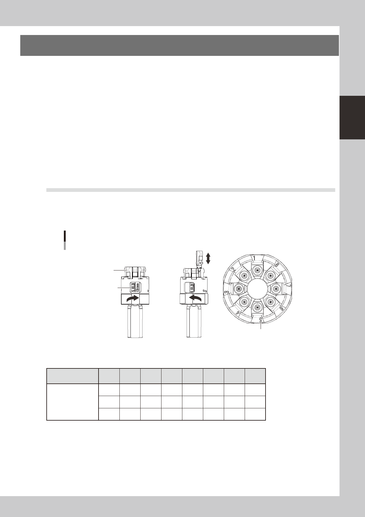
How to use the nozzle attach/detach tool for HS head
Usingthenozzleattach/detachtoolforHShead(hereaftercalledthe“tool”)allowsyoutoattach8nozzlesto
theHSheadordetachthematatime.Thistoolisusefulformaintenanceworkwhenthemachineisnot
equippedwithanozzlestation.
Clamp is closed
Nozzle
Clamp is open Top view of tool
Nozzle set position marking
Nozzle attach/detach tool
Marking to check nozzles
during attach/detach
(Heads H5, H13, H21)
53207-N5-00
n
Nozzle set position vs. head No.
Nozzle set position
marking No.
1 2 3 4 5 6 7 8
Head No.
1 2 3 4 5 6 7 8
9
10 11 12 13 14 15 16
17 18 19 20 21 22 23
24
2-2
2
Daily maintenance items
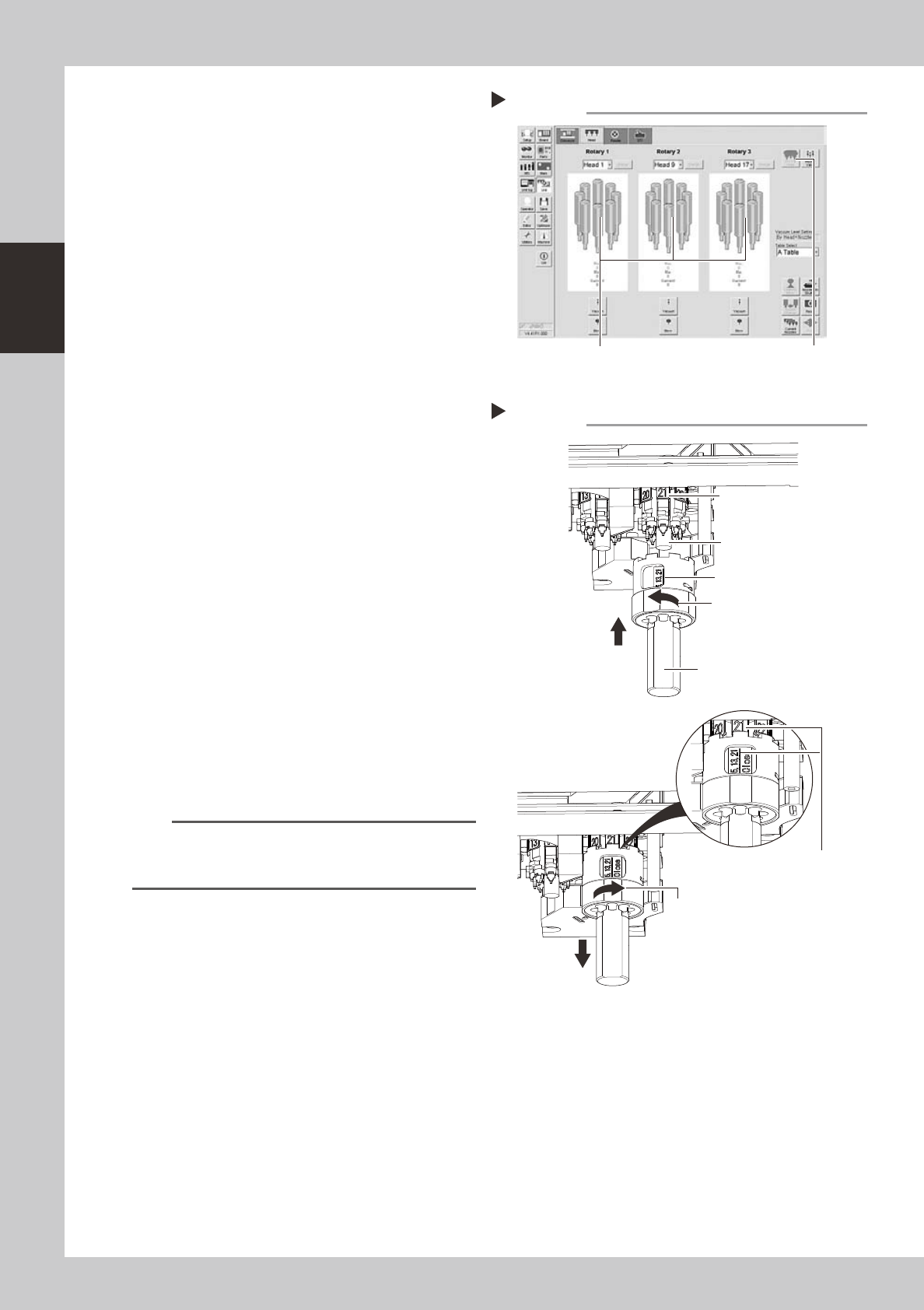
1
Move the heat to the nozzle attach/
detach position.
Open the [Unit]-[Head] tab and press the [All
First Head] button on the upper right of the
screen to change the first head.
54205-N5-00
e
2
Remove the feeder exchange
carriage.
Press the emergency stop button and then
remove the feeder exchange carriage from
the machine.
3
Remove the nozzles.
1. Move the head to a position where the
nozzles can be removed easily.
2. Open the clamp of the tool.
3. Holding the tool so that the marking
shown in the tool faces the front side,
align the tool with the spring holder and
raise it up against the heads.
4. Make sure the front head matches the
marking No. shown in the tool, close the
clamp of the tool, and pull the tool
down.
53206-N5-00
4
Perform the necessary work.
Perform maintenance of the nozzles and
shafts.
5
Reattach the nozzles.
1. Return the nozzles into the tool by
referring to the table showing the nozzle
set position vs. head No.
2. Reattach the nozzles by reversing the
removal procedure.
n
NOTE
If you are not sure of the nozzle set position, open the
Unit screen, press the [Required Nozzle] button in the
Utility group box, and check the nozzle list.
Removing the nozzles
Step 3
Marking “5, 13, 21”
Nozzle attach/detach tool
Open the clamp.
Close the clamp.
Make sure the front head
matches the marking No.
shown in the tool.
Front head facing you
Spring holder
Changing the first head of each rotary
Step 1
[All First Head] button
Heads H5, H13 and H21 are positioned toward you
(front side of machine).