YSM40 Mainte_E.pdf - 第63页
2-5 2 Daily maintenance items n How to check for clogged nozzles (on the [Unit]-[Head] tab screen) T heterm"cloggednozzle"usedhereindicatesthatmaterialsuchassolderisadheringtothenozzlehole,cau…
2-4
2
Daily maintenance items
1. Checking the nozzle
Solder sticking to the nozzle tip or a clogged nozzle hole can cause component pickup errors and
recognition errors. Poor nozzle spring action can also cause pickup and mounting errors. To prevent such
problems periodically inspect and clean each nozzle.
1.1 Check with software
n
How to check for a dirty nozzle (with the [Check Nozzle] button)
Theterm"dirtynozzle"asusedhereindicatesshinymaterialsuchassolderadheringtothenozzletip.This
shinyportionmightbemistakenforacomponentandcauserecognitionerrors.Tocheckforthisproblem,
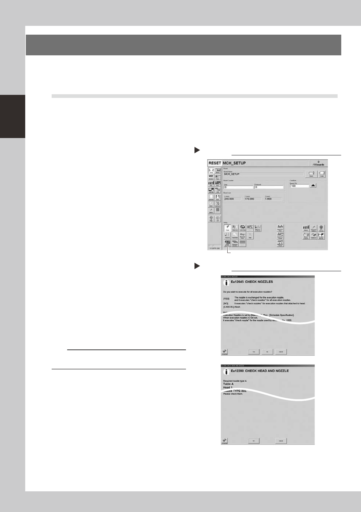
pressthe[CheckNozzles]buttononthe[Setup]screenwhilethenozzletippicksupnocomponents.The
camerafindstheextentofgrimeordirtonthenozzletip.
e
1
Move the head.
Press the emergency stop button and move
the head so the nozzle is at a position where
it can be easily replaced.
2
Press the [Check Nozzles] button as
follows.
1. Cancel emergency stop.
2. Open the [Setup] screen and press the
[Check Nozzles] button in "Utilities".
54200-N5-00
3
Select the item to be executed.
After checking the displayed message,
select the desired button.
n
When [Yes] was selected
Performsautonozzlechangeandchecksallrelevant
nozzles.
n
When [No] was selected
Checksrelevantnozzlesofallnozzlescurrently
attachedtothehead.
54201-N5-00
4
Check the message.
Clean the nozzle if the check shows it is dirty.
n
NOTE
The "Check Nozzles" function is usually set for "Type 502A
nozzles" before shipment.
Pressing the [Check Nozzles] button
Step 2
[Check Nozzles] button
Selecting the item to be executed
Step 3
When [No] was selected
2-5
2
Daily maintenance items
n
How to check for clogged nozzles (on the [Unit]-[Head] tab screen)
Theterm"cloggednozzle"usedhereindicatesthatmaterialsuchassolderisadheringtothenozzlehole,causingarise
innegativepressureevenifnocomponentisbeingpickedupbythenozzle.Thisstatemightcauseproblemssuchas
componentmountingerrors.Checkforcloggednozzleswiththefollowingprocedure,whichisdescribedusingtheType
502AMUHeadasanexample.
n
NOTE
When checking other nozzles and their vacuum levels, see the next section 1.1.1 “Vacuum level when nozzle is open”
in this chapter.
e
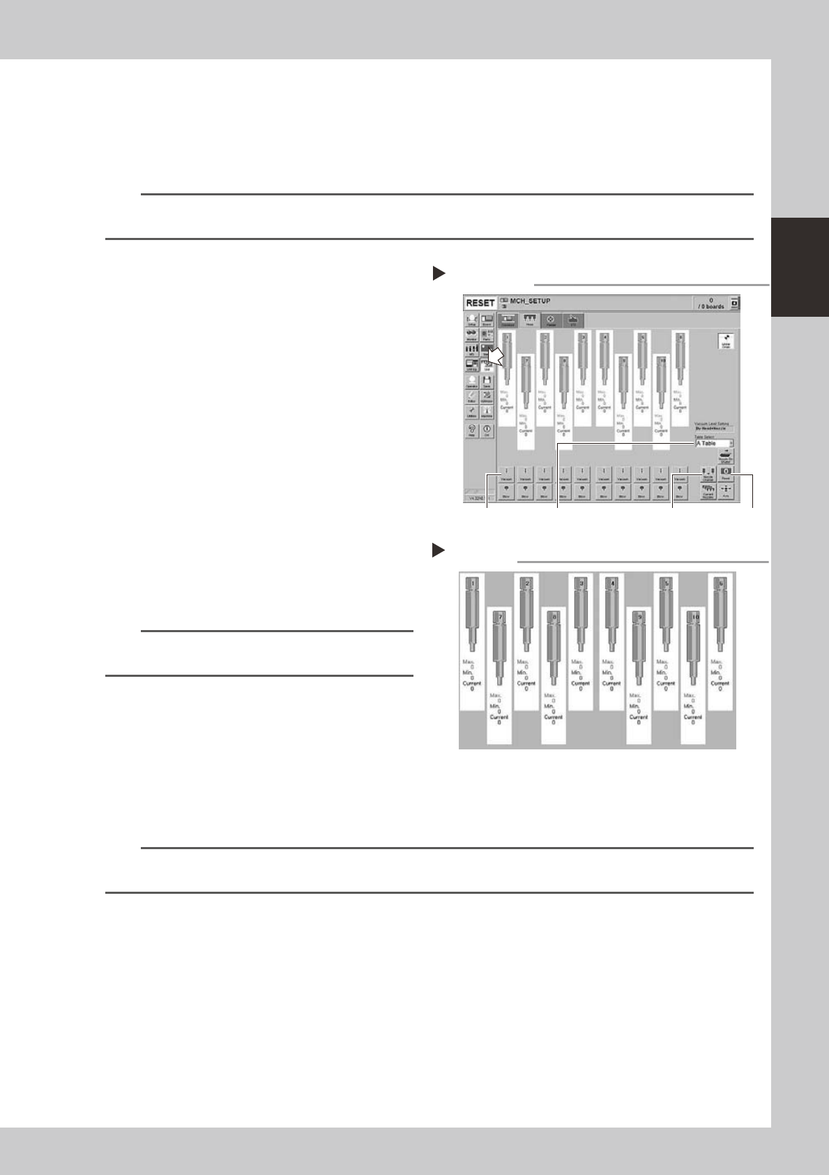
1
Attach the nozzle.
Press the emergency stop button and attach
Type 502A nozzles to all tables and heads.
When the machine has a nozzle station,
press the [Nozzle Change] button to change
the nozzles.
54202-N5-00
2
Reset the numerical figure.
Open the [Unit] - [Head] tab screen. Then
press the [Reset] button on the lower right of
the screen to reset the pickup level values.
Perform the table selection and reset the
pickup level values of all tables.
3
Generate negative pressure.
On the [Unit] - [Head] tab screen, set the
[Vacuum] buttons for all heads to ON. When
this value starts rising, wait 5 to 10 seconds
and set to OFF. Perform the table selection
and reset the pickup level values of all
tables.
n
NOTE
Only when checking the HS heads, generate negative
pressure for one head at a time.
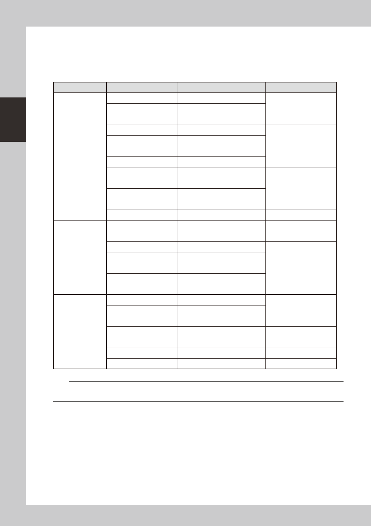
4
Check the vacuum levels.
Change the table sequentially to read all
"Max" values shown in red on the [Head] tab
screen. If this value is 75 or less then it is in
normal range. If higher than 75, then the
nozzle hole might be dirty and probably
needs cleaning.
54203-N5-00
n
NOTE
If a correct value cannot be obtained after cleaning even after performing steps 1 to 4, then the interior of the spline
shaft might be dirty. To check it, refer to the table on the right.
Negative pressure generation
Step 1 to 3
[Nozzle Change] button[Vacuum] button [Reset] button[Table selection] button
Negative pressure check
Step 4
2-6
2
Daily maintenance items
1.1.1 Vacuum level when nozzle is open
Thetablebelowshowsthevacuumlevelmeasuredwheneachnozzleisopen.
Thevaluesmightdifferslightlydependingontheairsourceandoperatingconditions.Usethesevaluesfor
referenceduringmaintenance.
n
Standard vacuum level when nozzle is open
Head Type Nozzle Standard value when nozzle is open Remarks
MU head
Type500A 180 or less
Standard nozzleType501A 120 or less
Type502A 75 or less
Type510A 180 or less
Narrow-pitch nozzle
Type511A 150 or less
Type512A 100 or less
Type513A 60 or less
Type503A/Type514A* 30 or less
Type504A/Type515A* 30 or less
Type506A/Type517A* 40 or less
Type507A/Type518A* 30 or less
No nozzle 30 or less
HS head
Type501A 120 or less
Standard nozzle
Type502A 75 or less
Type510A 165 or less
Narrow-pitch nozzle
Type511A 140 or less
Type512A 100 or less
Type513A 75 or less
No nozzle 50 or less
FL head
Type601A 120 or less
Type602A 75 or less
Type603A* 30 or less
Type604A* 30 or less
With O-ring
Type605A* 30 or less
Type606A* 40 or less With V-notch
No nozzle 30 or less
n
NOTE
If the vacuum levels of the nozzles marked by asterisk (*) exceed the above standard values, the air path in the head
might be clogged.