YSM40 Mainte_E.pdf - 第82页
3-14 3 Periodic maintenance items 5 Clean the nozzle shaft and main holder . 1. Use a lint-free cloth to wipe off the dust and dirt on the nozzle shaft. 2. Use a lint-free cloth to wipe off the dust and dirt on main hold…
3-13
3
Periodic maintenance items
2.1 Rotary unit
Asageneralguide,themainrotaryandshaftnozzlesshouldbecleanedevery3months,althoughthismay
varysomewhatdependingontheairsupplyconditionsandtheoperatingtime.
2.1.1 Cleaning the rotary unit
e
1
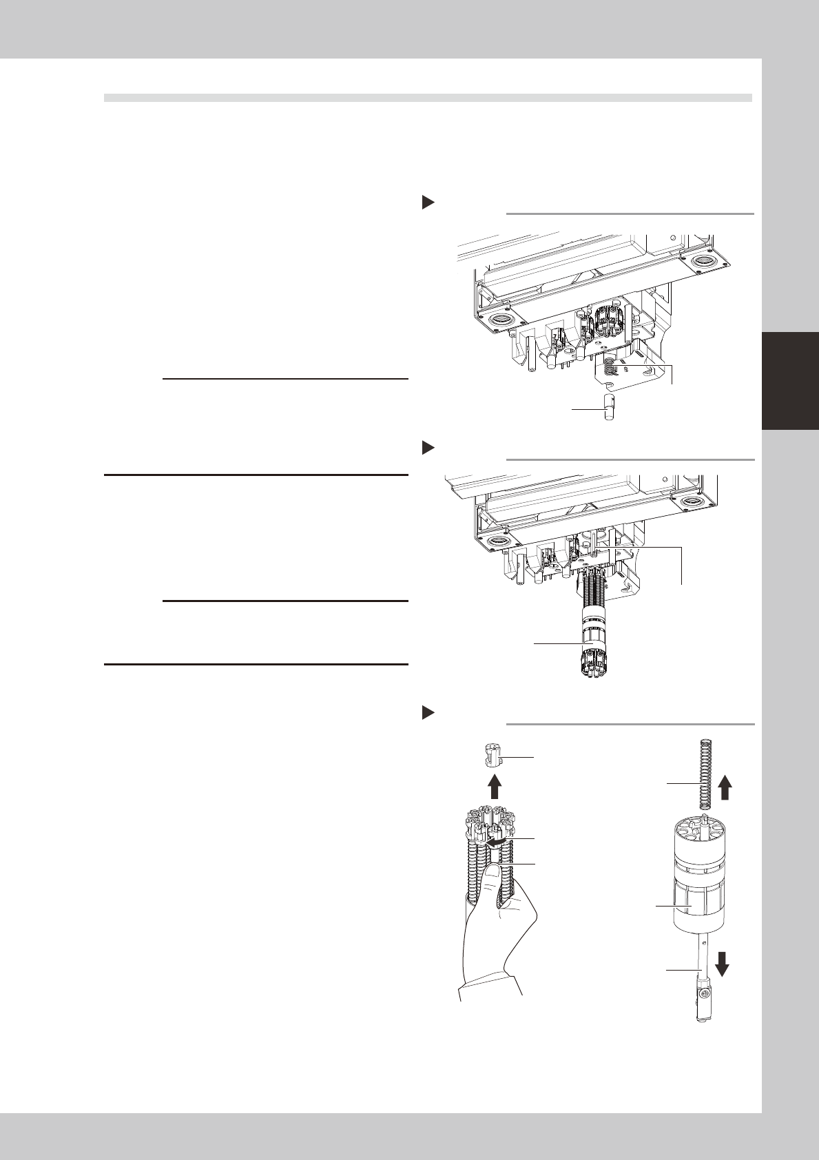
Remove the spring holder.
1. While pressing up the spring holder shown
in the figure at right, turn it to the right.
2. Remove the spring holder and the spring.
53311-N5-10
2
Remove the rotary.
Pull out the rotary from the head unit.
53312-N5-10
c
view lighting unit and other parts.
can easily return it in the original position after
cleaning.
3
Remove the mount block.
With the spring held down as shown in the
figure at right, turn the mount block 90
degrees and pull it out upward.
53322-N5-00
c
To prevent the spring and mount block from falling out
the spring during removal of the mount block.
4
Pull out the nozzle shafts and
springs.
Pull out all nozzle shafts and springs from the
main holder.
Removing the spring holder
Step 1
Spring holder
Spring
Removing the rotary
Step 2
Rotary
Main shaft
Removing the mount block
Step 3
Hold down the spring
Spring
Turn 90 degrees
Main holder
Nozzle shaft
Mount block
3-14
3
Periodic maintenance items
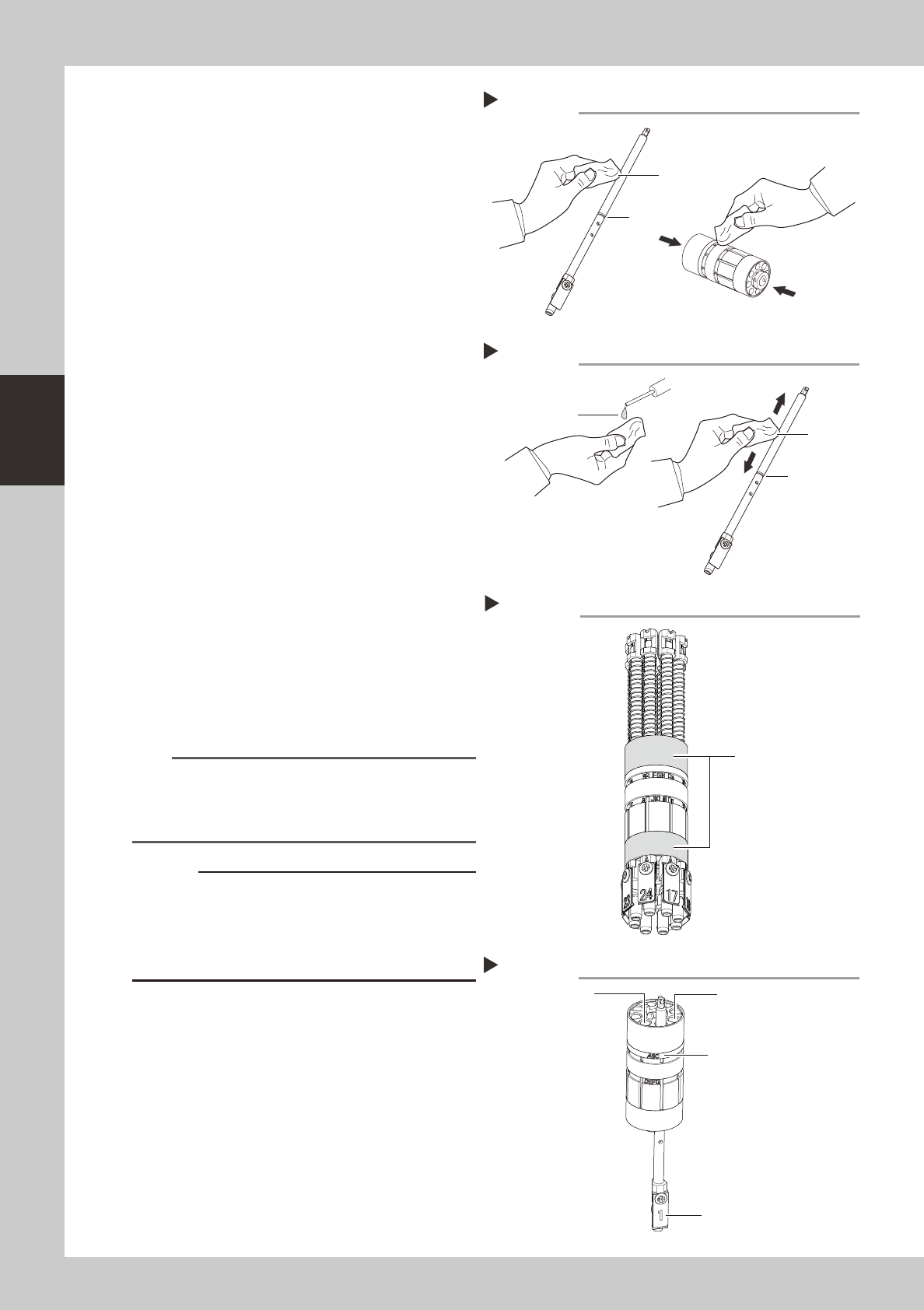
5
Clean the nozzle shaft and main
holder.
1. Use a lint-free cloth to wipe off the dust
and dirt on the nozzle shaft.
2. Use a lint-free cloth to wipe off the dust
and dirt on main holder. Wipe the
surfaces indicated by an arrow shown in
the figure at right.
3. Clean the spring by air blow.
53323-N5-00
6
Lubricate the nozzle shafts.
1. Use a lint-free cloth dampened with
turbine oil to lubricate the entire nozzle
shaft.
2. If turbine oil has collected in the groove,
lightly wipe it off.
53324-N5-10
7
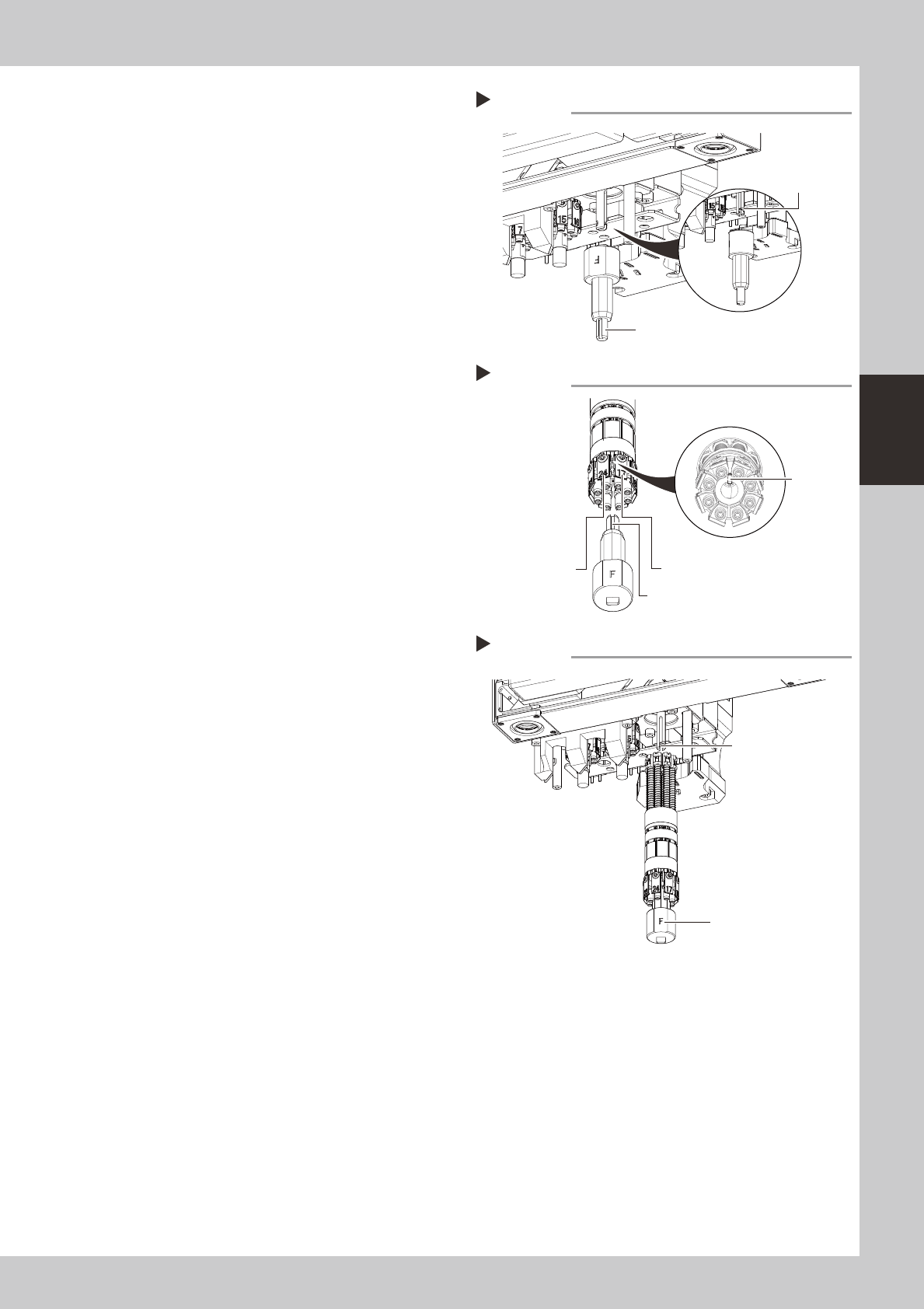
Apply the grease to the main
holder.
Apply the grease (LG2) thinly to the rotary
support shown in the figure on the right.
533E1-N5-00
8
Insert the nozzle shafts into the
main holder.
A serial number is marked on the main
holder.
Starting from the position to the right of the
serial number marking, insert each nozzle
shaft into place in the order of numbers (1, 2,
3 …) as marked on the leaf spring.
53330-N5-00
TIP
Shaft number order of each head
Head 1: 1, 2, 3, and so on
Head 2: 9, 10, 11, and so on
Head 3: 17, 18, 19, and so on
c
position.
If the rank marking on the main holder does not match
operation or mounting accuracy failure.
9
Secure the nozzle shafts.
Reinstall the spring and mount block to
secure each nozzle shaft.
Lint-free cloth
Cleaning the nozzle shaft and main holder
Step 5
Groove
Lint-free
cloth
Lubricating the nozzle shaft
Step 6
Groove
Turbine oil
Inserting nozzle shafts
Step 8
Serial number
(marking)
Leaf spring
(Head number marking)
Head 2
Head 8
Applying the grease
Step 7
Greasing location
(Rotary support)
3-15
3
Periodic maintenance items
0
Change the orientation of the
keyway in the main shaft.
Using the rotary head attach/detach tool,
turn the main shaft so that the keyway faces
the front side of the machine to make the
following steps easier.
533B2-N5-00
q
Install the rotary head attach/
detach tool.
Insert the rotary head attach/detach tool
into the rotary while aligning its keyway with
the rotary’s pin. The “F” side of the tool
should be positioned between the first and
last heads.
533B3-N5-00
w
Insert the rotary onto the main
shaft.
Align the “F” side of the rotary head attach/
detach tool with the keyway in the main
shaft, and then insert the rotary onto the
main shaft.
533B4-N5-00
e
Pull out the rotary head attach/
detach tool.
r
Reattach the spring holder.
Reverse step 1 to reattach the spring holder.
t
Make sure the rotary is properly
installed.
Turn the rotary by hand one turn to the right
and one turn to the left. If the rotary does
not turn smoothly, then pull it out again.
Check the position of the mount block and
reinstall the rotary using the same procedure
from step 9.
Installing the tool
Step 11
Pin
First head
Last head
Keyway
Installing the rotary
Step 12
Main shaft keyway
“F” marking
Changing the main shaft orientation
Step 10
Main shaft keyway
Rotary head attach/detach tool