YSM40 Mainte_E.pdf - 第87页
3-19 3 Periodic maintenance items 2.2 X-axis T hissectionexplainstheX-axisinspection,cleaning,andlubricationprocedures.Fordetailsregarding lubricationpointsandthelubricationcondition,seesection5&quo…
3-18
3
Periodic maintenance items
9
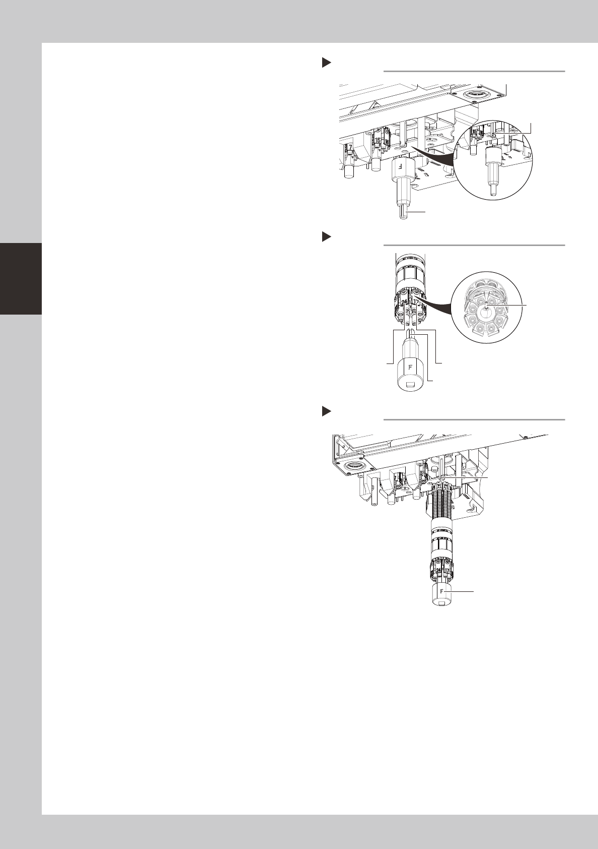
Change the orientation of the
keyway in the main shaft.
Use the rotary head attach/detach tool to
turn the keyway so that it directly faces this
machine. (The keyway in the main shaft is
located at twelve o'clock position when
viewed from the lower portion.)
533E9-N5-00
0
Install the rotary head attach/
detach tool.
Insert the rotary head attach/detach tool
into the rotary while aligning its keyway with
the rotary’s pin. The “F” side of the tool
should be positioned between the first and
last heads.
533F1-N5-00
q
Insert the rotary onto the main
shaft.
Align the “F” side of the rotary head attach/
detach tool with the keyway in the main
shaft, and then insert the rotary onto the
main shaft.
533F2-N5-00
w
Pull out the rotary head attach/
detach tool.
e
Reattach the spring holder.
Reverse step 1 to reattach the spring holder.
r
Make sure the rotary is properly
installed.
Turn the rotary by hand one turn to the right
and one turn to the left. If the rotary does
not turn smoothly, then pull it out again.
Check the position of the mount block and
reinstall the rotary using the same procedure
from step 9.
Step 9
Changing the main shaft orientation
Main shaft keyway
Rotary head attach/detach tool
Step 10
Installing the tool
Pin
First head
Last head
Keyway
Step 11
Installing the rotary
Main shaft keyway
“F” marking
3-19
3
Periodic maintenance items
2.2 X-axis
ThissectionexplainstheX-axisinspection,cleaning,andlubricationprocedures.Fordetailsregarding
lubricationpointsandthelubricationcondition,seesection5"LubricationPointsandSchedule".Theuser
mustprovidethegreasegun(standardnozzleand30°bendnozzle)andtheprescribedgrease(NSL).
2.2.1 Cleaning and greasing the X-axis ball screw (4-beam type)
1
Make the preparations for the cleaning and greasing work.
e
1. Take off all accessories susceptible to the magnetic fields, such as a wristwatch and/or magnetic ID
card.
2. Press the emergency stop button to put the machine in the emergency stop state.
3. Detach the batch change carriage.
4. Place a square cloth on the Y-axis linear area and the push-up plate.
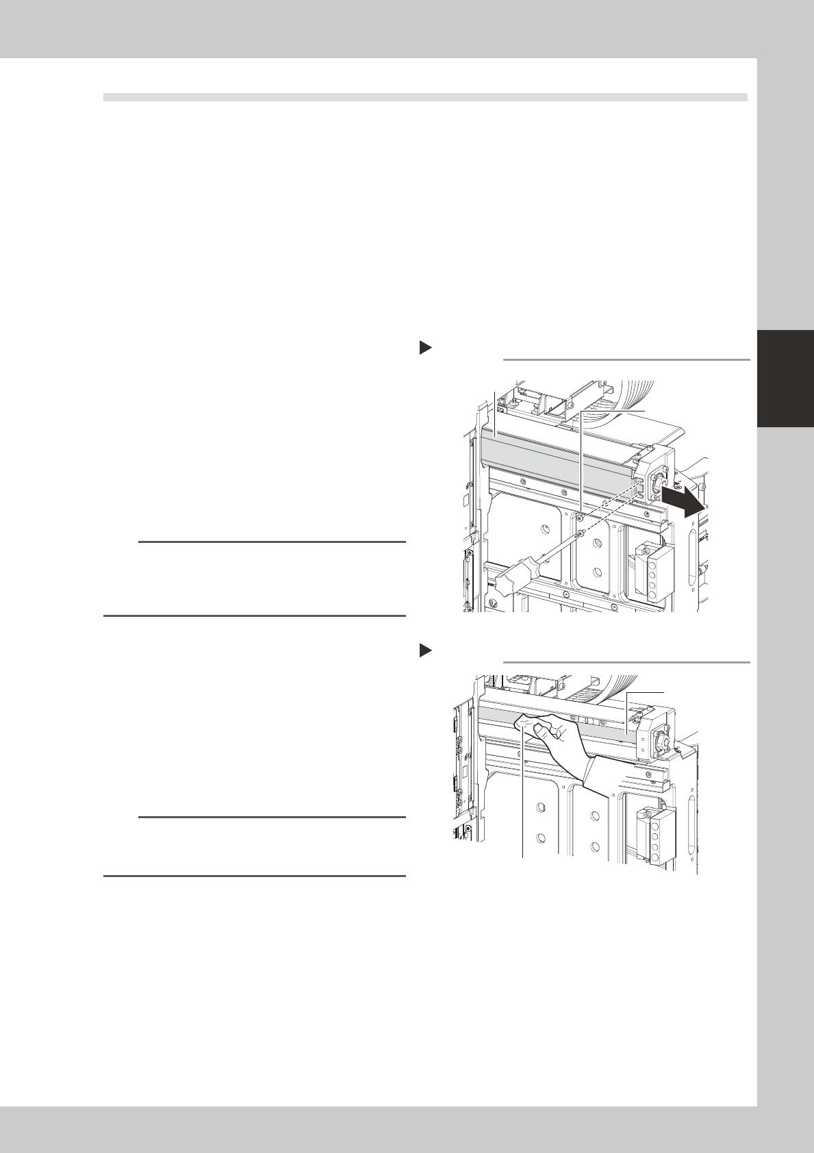
2
Remove the grease spattering
prevention cover.
Remove the X-axis grease spatter prevention
cover.
1. Use a Phillips screwdriver to remove the
screws which secure the spatter
prevention cover (at machine center
side).
2. Remove the spatter prevention cover by
sliding it toward the machine center.
53357-N5-00
TIP
Reattach the X-axis grease spatter prevention cover by
reversing the above removal procedure. Attach by
pressing the end of the cover which is at the motor
side.
3
Clean the ball screws.
1. Grasp the movement handle and move
the head unit to one end.
2. Wipe away the old grease and dirt from
the ball screw with a lint-free cloth or
paper towel (for clean room use).
3. Move the head unit to the opposite end,
then wipe the opposite-side ball screw.
53358-N5-00
n
NOTE
When cleaning the ball screw, carefully clean its
groove area as well. Be sure that the cloth, etc., being
used to clean the ball screw does not produce lint, etc.
Removing the spatter prevention cover
Step 2
Grease spattering
prevention cover
Cover securing screws
Cleaning the ball screw
Step 3
Cloth
Ball screw
3-20
3
Periodic maintenance items
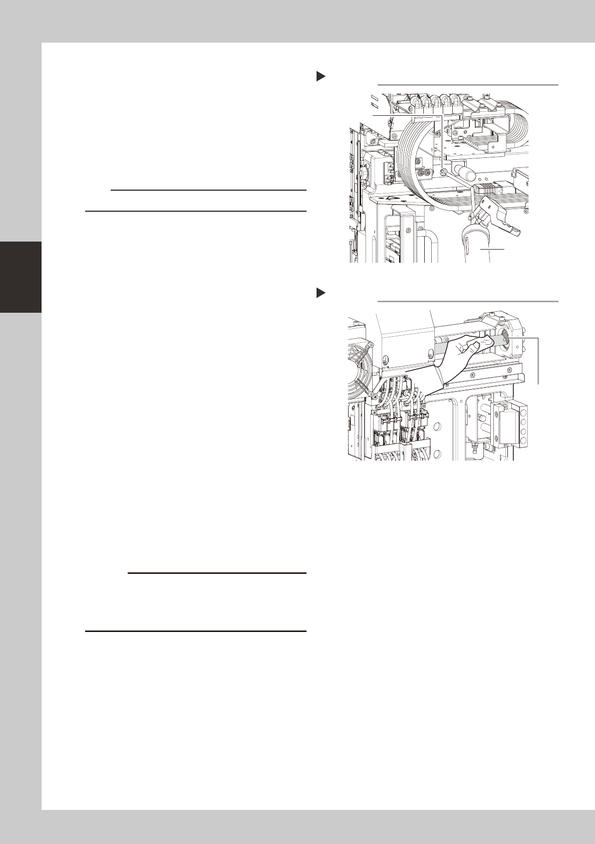
4
Apply grease.
1. As shown in the figure at right, move the
head unit by hand to a position where
the grease nipple is visible through the
access window.
2. Use a grease gun (30° bend type) to
inject the prescribed grease at the
grease nipple.
53359-N5-00
n
NOTE
Inject until the grease begins to seep out from the gap.
5
Wipe off the excess grease.
1. Grasp the movement handle and move
the head unit to one end.
2. Wipe all excess grease from the ball
screw and nut end faces.
3. Move the head unit to the opposite end
and wipe all excess grease from the
opposite-end ball screw and nut end
faces.
53360-N5-00
6
Perform a warm-up.
1. Remove the square cloth.
2. Reattach the spatter prevention cover.
3. Close the machine's cover, attach the
batch change carriage, then release the
"Emergency Stop" status.
4. Open the Warm-up screen, and perform
the warm-up operation for approximately
8 minutes.
e
7
Check the grease condition.
After stopping the machine operation,
remove the grease spattering prevention
cover and wipe off grease which has
collected on the ball screw and the ball
screw end face.
c
Repeat Steps 6 and 7 until grease accumulations no
accumulations present could cause the grease to
spatter.
Applying grease
Step 4
Grease nipple
Grease gun
(30° bend type)
Wiping off the excess grease
Step 5
Excess
grease