YSM40 Mainte_E.pdf - 第90页
3-22 3 Periodic maintenance items 5 Wipe off the ex cess grease. 1. Grasp the movement handle and move the head unit to one end. 2. Wipe all excess grease from the ball screw and nut end faces. 3. Move the head unit to t…
3-21
3
Periodic maintenance items
2.2.2 Cleaning and greasing the X-axis ball screw (2-beam type)
1
Make the preparations for the cleaning and greasing work.
e
1. Take off all accessories susceptible to the magnetic fields, such as a wristwatch and/or magnetic ID
card.
2. Press the emergency stop button to put the machine in the emergency stop state.
3. Detach the batch change carriage.
4. Place a square cloth on the Y-axis linear area and the push-up plate.
2
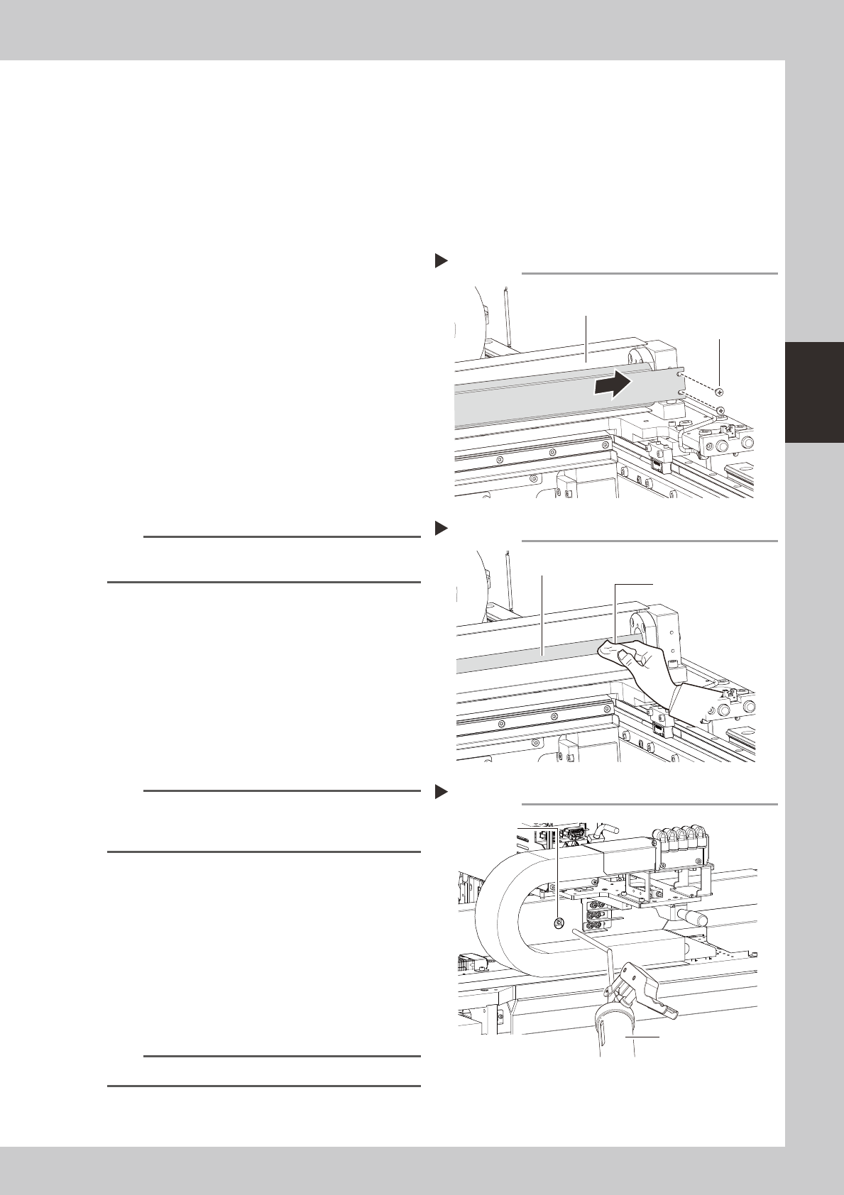
Remove the grease spattering
prevention cover.
Remove the X-axis grease spatter prevention
cover.
1. Use a Phillips screwdriver to remove the
screws that secure the grease spattering
prevention cover (at the motor side).
2. Move the head unit to the motor side.
3. Use a Phillips screwdriver to remove the
screws that secure the grease spattering
prevention cover (at the side opposite to
the motor side), then remove the grease
spattering prevention cover by pulling it
out.
53390-N5-00
TIP
Reattach the X-axis grease spatter prevention cover by
reversing the above removal procedure.
3
Clean the ball screws.
1. Grasp the movement handle and move
the head unit to one end.
2. Wipe away the old grease and dirt from
the ball screw with a lint-free cloth or
paper towel (for clean room use).
3. Move the head unit to the opposite end,
then wipe the opposite-side ball screw.
53391-N5-00
n
NOTE
When cleaning the ball screw, carefully clean its
groove area as well. Be sure that the cloth, etc., being
used to clean the ball screw does not produce lint, etc.
4
Apply grease.
1. As shown in the figure at right, move the
head unit by hand to a position where
the grease nipple is visible through the
access window.
2. Use a grease gun (30° bend type) to
inject the prescribed grease at the
grease nipple.
53392-N5-00
n
NOTE
Inject until the grease begins to seep out from the gap.
Removing the spatter prevention cover
Step 2
Grease spattering prevention cover
Cover securing screws
Cleaning the ball screw
Step 3
Cloth
Ball screw
Applying grease
Step 4
Grease nipple
Grease gun
(30° bend type)
3-22
3
Periodic maintenance items
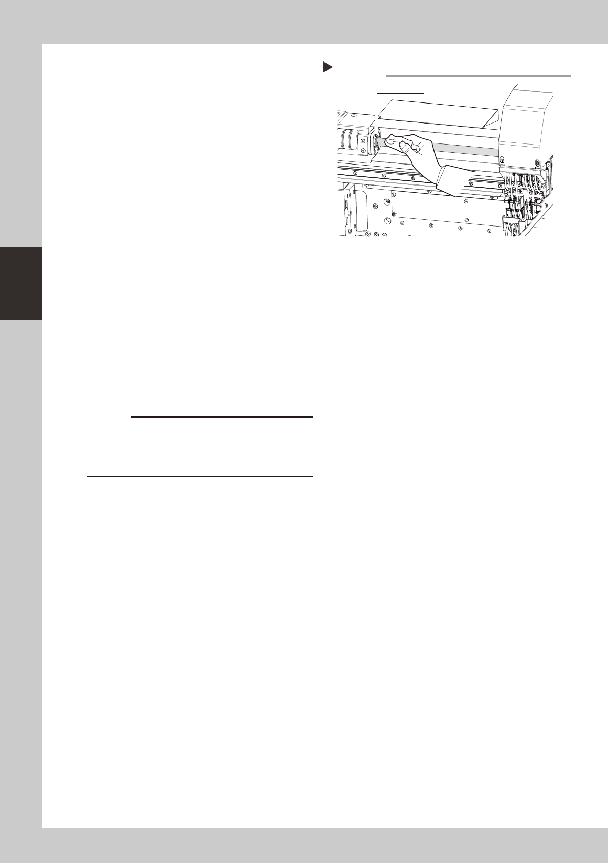
5
Wipe off the excess grease.
1. Grasp the movement handle and move
the head unit to one end.
2. Wipe all excess grease from the ball
screw and nut end faces.
3. Move the head unit to the opposite end
and wipe all excess grease from the
opposite-end ball screw and nut end
faces.
53360-N5-00
6
Perform a warm-up.
1. Remove the square cloth.
2. Reattach the spatter prevention cover.
3. Close the machine's cover, attach the
batch change carriage, then release the
"Emergency Stop" status.
4. Open the Warm-up screen, and perform
the warm-up operation for approximately
8 minutes.
e
7
Check the grease condition.
After stopping the machine operation,
remove the grease spattering prevention
cover and wipe off grease which has
collected on the ball screw and the ball
screw end face.
c
Repeat Steps 6 and 7 until grease accumulations no
accumulations present could cause the grease to
spatter.
Wiping off the excess grease
Step 5
Excess grease
3-23
3
Periodic maintenance items
2.2.3 Cleaning and lubricating the X-axis guide (4-beam type)
1
Make the preparations for the cleaning and greasing work.
1. Take off all accessories susceptible to the magnetic fields, such as a wristwatch and/or magnetic ID
card.
e
2. Press the emergency stop button to put the machine in the emergency stop state.
3. Detach the batch change carriage.
4. Place a square cloth on the Y-axis linear area and the push-up plate.
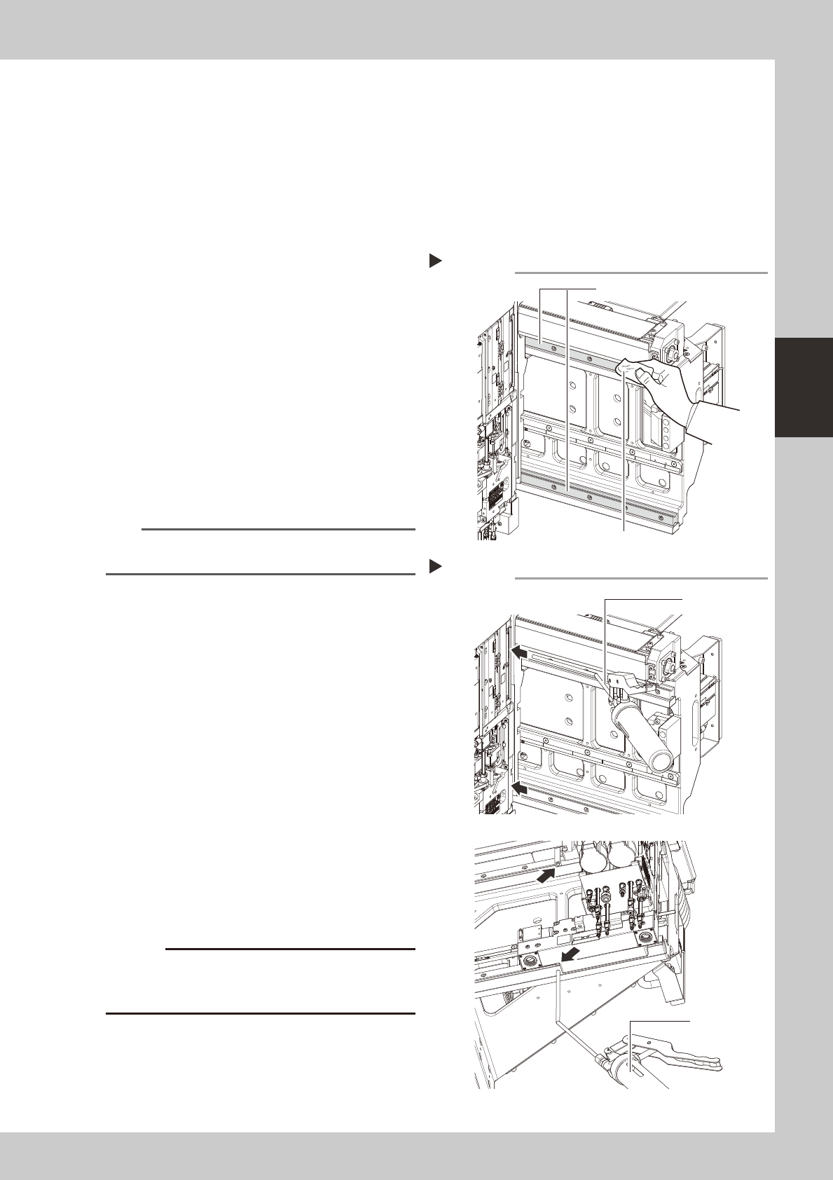
2
Clean the guide.
1. Grasp the movement handle and move
the head unit to one end.
2. Using a paper cloth (clean room type)
which produces no lint, wipe the old
grease and soiling from the entire guide.
3. Move the head unit to the opposite side,
then clean the opposite-side guide.
53361-N5-00
3
Inject the grease.
Using a grease gun (bend type), inject the
prescribed grease (NSL) at the X-axis guide's
grease nipples (4 nipples).
53362-N5-00
n
NOTE
The head unit must be at the motor side when injecting
grease.
4
Remove excess grease.
1. Grasp the movement handle and move
the head unit to one end.
2. Wipe off the excess grease from the
guide end face.
3. Move the head unit to the opposite side,
then wipe the excess grease off the
opposite-side guide end face.
5
Check the grease condition.
1. Remove the square cloth.
2. Close the machine's cover, attach the
batch change carriage, then release the
"Emergency Stop" status.
e
3. Open the Warm-up screen, and perform
the warm-up operation for approximately
8 minutes. After the machine stops, wipe
off grease which has collected on the
guide end face.
c
Repeat Step 5 until grease accumulations no longer
present could cause the grease to spatter.
Cleaning the guide
Step 2
Cloth
Guide
Injecting the grease
Step 3
Front side
Bottom side, rear side
Grease gun
(bend type)
Grease gun
(bend type)