00191663.pdf - 第19页
Retrofit Instructions 80F5 DCA Option 05/99 issue 1 Overview 19 1 Fig. 1 - 2 MVS 340 analysis unit in the control unit (1) Vision s ystem, PCB and c omponent an alysis unit (2) COM2 (3) COM1 (4) HS 3L commun ications con…
DCA Option Retrofit Instructions 80F5
05/99 issue
18
1
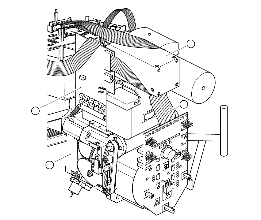
Fig. 1 - 1 DCA camera system
Key to Fig. 1 - 1
(1) FC camera 16 x 16
(2) Illumination control board
(3) 6-nozzle revolver head
(4) Ribbon cable for the star motor
1
2
3
4
Retrofit Instructions 80F5 DCA Option
05/99 issue 1 Overview
19
1
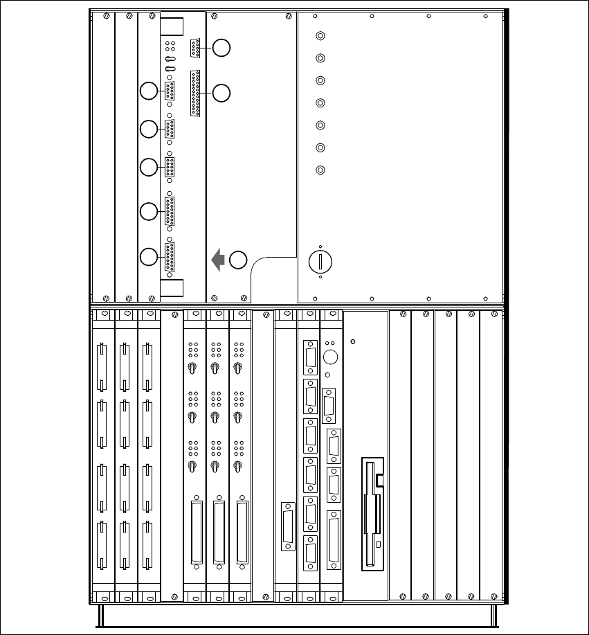
Fig. 1 - 2 MVS 340 analysis unit in the control unit
(1) Vision system, PCB and component analysis unit
(2) COM2
(3) COM1
(4) HS3L communications connector
(5) Monitor connector (SVGA)
(6) Trigger / Flash connector
(7) Camera connectors: (1) PCB camera (3) Cmpt. camera, 6-nozzle revolver head
(8) Camera connectors: (2) P&P head camera (4) FC camera, Pick&Place head
+24V
-15V
+15V
-12V
+12V
Achsservice
Servo
Aus
Servo
Aus
Servo
Aus
Servo
Aus
Servo
Aus
Servo
Aus
AUI
Servo
Aus
Servo
Aus
Servo
Aus
Kamera
Kamera
2/4
1/3
AUX
Batterie
3,8V
GND
S-COM
S-COM
Reset
Abort
+5V
DISPLAY
HS3L
2
1
MVS
ICOS
X5se
X5sg
X4se X3se
X4sg X3sg
X3tq
X3sn
X3sm
X2sp
X2se
X2sg
2
3
8
7
6
5
4
1
X2sfX3sfX4sfX5sf
Achsservice
Achsservice
Harddisk
X7sa X6sa X5sa
X4sa
S-COM 2LPT S-COM 1
VGA
Tast
Reset
Floppy
S-COM 1 S-COM 2 S-COM 3 S-COM 4 CAN-Bus CAN-Bus
X2sd X3sd X4sd X5sd X6sd X7sd
X3

DCA Option Retrofit Instructions 80F5
05/99 issue
20
(9) Battery
(10) Power supply unit
2 Technical data for the component vision system
for flip-chips, bare dies and standard components
on the 6-nozzle revolver head (DCA option)
Camera type: SONY XC75CE 2
Number of pixels: 570 x 570 2
Field of vision: 15.7mm x 15.7 mm 2
Illumination method: Front lighting (red light), 4 LED planes (even, flat,
medium, steep) 2
Image processing: HALE grey scale method (H
igh Accuracy Lead Extraction) 2
Monitor: RGB (VGA mode) 640 x 484 pixels 2
Component size: 0.25 mm x 0.5 mm ... 13 mm x 13 mm 2
Range of components
that can be detected: Flip-chips, bare dies, components up to 13mm x 13mm 2
Minimum lead spacing 0.2 mm 2
Minimum ball diameter: 110
µm 2
System sensor type (SST) 14 2
3 Line and station computer requirements
Line computer software ≥ 5.01
Station computer software
≥ 4.05
MC software
≥ 4.05
CAN firmware 2.2
SITEST
≥ 4.05
Nozzle types 750 - 759 3