00191663.pdf - 第23页
Retrofit Instructions 80F5 DCA Option 05/99 issue 8 Dismantling the 24 x 24 component camera 23 7 Fig. 7 - 1 Dismantling the cover 8 Disman tling the 24 x 24 co mponen t camera È Detach the co nnectors o f the two ribbon…
DCA Option Retrofit Instructions 80F5
05/99 issue
22
5 Tools and equipment
– Set of Allen keys, DIN 911
– SITEST program, version 4.05 or higher
6Parts
DCA package for SIPLACE F5 6-segment revolver head, item no. 00117130-02, consisting of: 6
– 16 x 16 FC camera, item no. 00337450-01
– Complete cover for flip-chip camera, item no. 00337697-02
– MVS 340 VME F5 DCA V2144E, item no. 00341201-03
– EXPANDO PT 30-0 flexible tubing, item no. 00344962-01
– SP6/12 digital control cable with FC camera, item no. 00337804-01
– SIPLACE 80F5 DCA service box, item no. 00341616-01
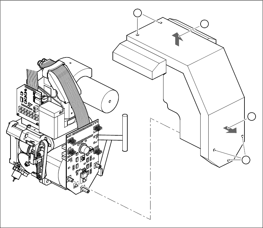
7 Dismantling the cover
È Switch off the placement system and secure to prevent reclosing as described in section 4.
È Remove the five M3x5 hexagon socket-head screws for fixing the cover (see Fig. 7 - 1, point A)
È Pull the cover towards you slightly in the horizontal direction (see Fig. 7 - 1, point B).
È Lift up the cover to remove (see Fig. 7 - 1, point C).
Retrofit Instructions 80F5 DCA Option
05/99 issue 8 Dismantling the 24x24 component camera
23
7
Fig. 7 - 1 Dismantling the cover
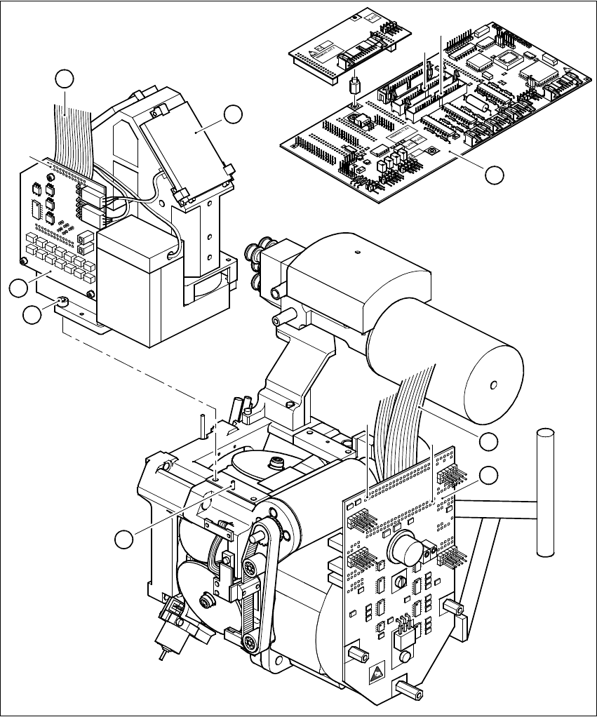
8 Dismantling the 24x24 component camera
È Detach the connectors of the two ribbon cables (item 6 in Fig. 7 - 1):
X13 and X14 on the head board (item 1 in Fig. 7 - 1)
X1 and X2 on the adapter board (item 5 in Fig. 7 - 1)
È Detach the connector of the ribbon cable (item 4 in Fig. 7 - 1) from plug X3 of the illumination
control unit.
È Loosen the four M4x10 hexagon socket-head screws (item 7 in Fig. 7 - 1)
È Carefully lift the component camera off the revolver head.
8
8
8
B
C
A
A
DCA Option Retrofit Instructions 80F5
05/99 issue
24
8
Fig. 8 - 1 Dismantling the component camera 24x24
Key to Fig. 8 - 1
(1) SP6-12 head board, digital (item no. 00330647)
(2) 24 x 24 component camera
(3) Illumination control unit
(4) Ribbon cable, illumination control unit - head board
1
2
X14
X13
3
4
X3
7
5
X1
X2
6
8