00191663.pdf - 第24页
DCA Option Retrofit Instructions 80F5 05/99 issue 24 8 Fig. 8 - 1 Dismantling the component camera 24 x 24 Key to Fig. 8 - 1 (1) SP6- 12 head bo ard, digi tal (item no. 00 330647) (2) 24 x 24 comp onent cam era (3) Illum…
Retrofit Instructions 80F5 DCA Option
05/99 issue 8 Dismantling the 24x24 component camera
23
7
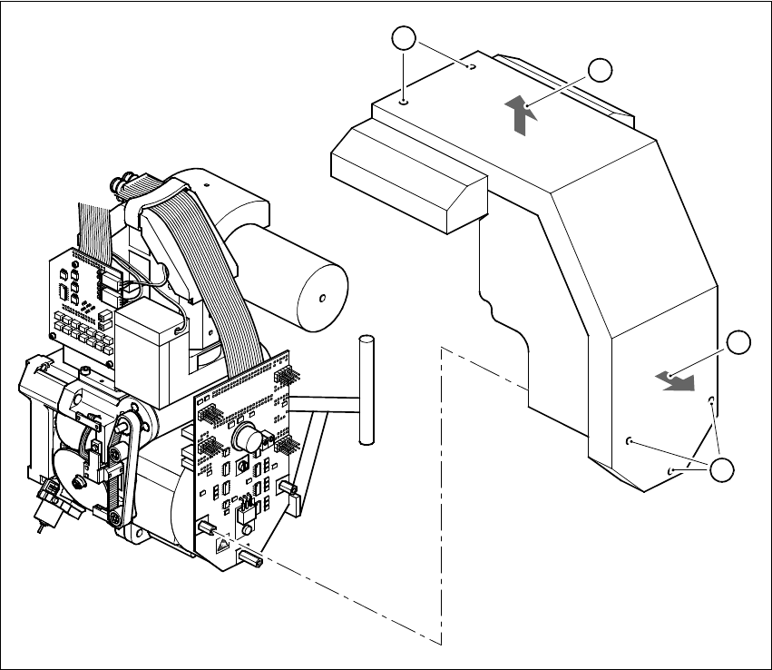
Fig. 7 - 1 Dismantling the cover
8 Dismantling the 24x24 component camera
È Detach the connectors of the two ribbon cables (item 6 in Fig. 7 - 1):
X13 and X14 on the head board (item 1 in Fig. 7 - 1)
X1 and X2 on the adapter board (item 5 in Fig. 7 - 1)
È Detach the connector of the ribbon cable (item 4 in Fig. 7 - 1) from plug X3 of the illumination
control unit.
È Loosen the four M4x10 hexagon socket-head screws (item 7 in Fig. 7 - 1)
È Carefully lift the component camera off the revolver head.
8
8
8
B
C
A
A
DCA Option Retrofit Instructions 80F5
05/99 issue
24
8
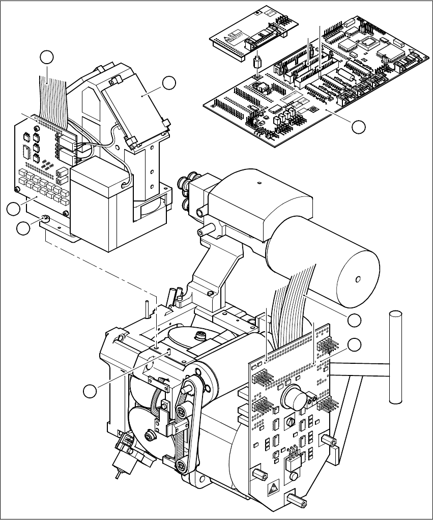
Fig. 8 - 1 Dismantling the component camera 24x24
Key to Fig. 8 - 1
(1) SP6-12 head board, digital (item no. 00330647)
(2) 24 x 24 component camera
(3) Illumination control unit
(4) Ribbon cable, illumination control unit - head board
1
2
X14
X13
3
4
X3
7
5
X1
X2
6
8
Retrofit Instructions 80F5 DCA Option
05/99 issue 9 Fitting the 16x16 FC camera
25
(5) SP6-12 adapter board, digital (item no. 00330648)
(6) Ribbon cable Head board X14 - adapter board X1
Head board X13 - adapter board X2
(7) M4x10 hexagon socket-head screw, 4 x
(8) Parallel pin, 2 x
9 Fitting the 16x16 FC camera
È Before you place the camera on the revolver head check that the contact surfaces are clean.
È Place the FC camera carefully on the revolver head.
È Make sure that you do not tilt the FC camera and that the parallel pins slide into the holes in
the FC camera housing.
È Push the FC camera lightly against the revolver head until it reaches the stop.
È Use the four M4x10 hexagon socket-head screws (item 7 in Fig. 8 - 1) to fix the FC camera to
the revolver head.
È Fix the two new ribbon cables for the star motor as follows:
– Connect plug X2 with strain relief clip of cable 00337804-W2 to plug X2 on the adapter
board (item 5 in Fig. 8 - 1).
– Connect plug X1 with strain relief clip of cable 00337804-W1 to plug X1 on the adapter
board (item 5 in Fig. 8 - 1).
È Connect plug X13 of cable 00337804-W2 to plug X13 on the head board (item 1 in Fig. 8 - 1).
È Connect plug X14 of cable 00337804-W1 to plug X14 on the head board (item 1 in Fig. 8 - 1).
È Connect the ribbon cable of the illumination control unit (item 4 in Fig. 8 - 1) to plug X3 on the
illumination control board (item 3 in Fig. 8 - 1).