00191663.pdf - 第25页
Retrofit Instructions 80F5 DCA Option 05/99 issue 9 Fitting t he 16 x 16 FC camera 25 (5) S P6-12 ad apter board, digital (i tem no. 0033 0648) (6) Ri bbon cabl e Head boa rd X14 - ad apter boa rd X1 Head board X13 - ad …
DCA Option Retrofit Instructions 80F5
05/99 issue
24
8
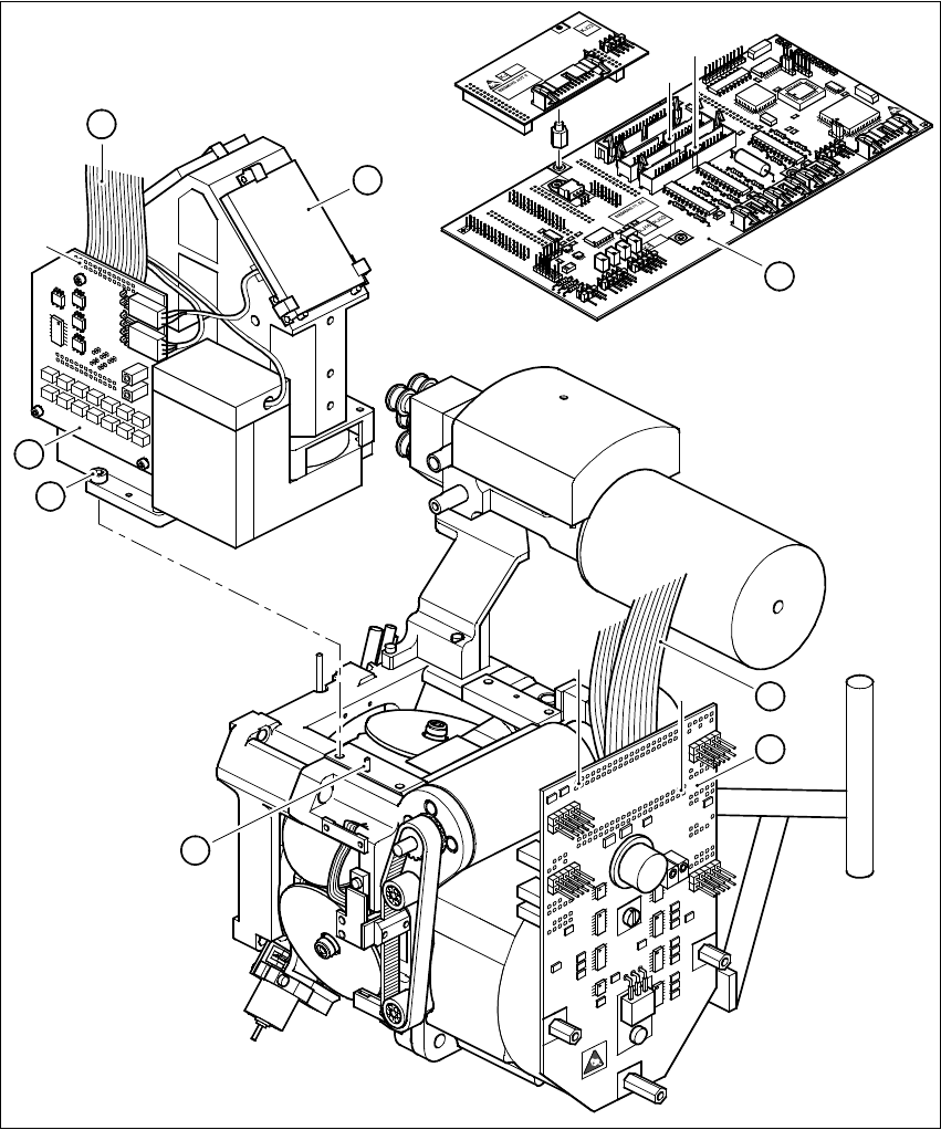
Fig. 8 - 1 Dismantling the component camera 24x24
Key to Fig. 8 - 1
(1) SP6-12 head board, digital (item no. 00330647)
(2) 24 x 24 component camera
(3) Illumination control unit
(4) Ribbon cable, illumination control unit - head board
1
2
X14
X13
3
4
X3
7
5
X1
X2
6
8
Retrofit Instructions 80F5 DCA Option
05/99 issue 9 Fitting the 16x16 FC camera
25
(5) SP6-12 adapter board, digital (item no. 00330648)
(6) Ribbon cable Head board X14 - adapter board X1
Head board X13 - adapter board X2
(7) M4x10 hexagon socket-head screw, 4 x
(8) Parallel pin, 2 x
9 Fitting the 16x16 FC camera
È Before you place the camera on the revolver head check that the contact surfaces are clean.
È Place the FC camera carefully on the revolver head.
È Make sure that you do not tilt the FC camera and that the parallel pins slide into the holes in
the FC camera housing.
È Push the FC camera lightly against the revolver head until it reaches the stop.
È Use the four M4x10 hexagon socket-head screws (item 7 in Fig. 8 - 1) to fix the FC camera to
the revolver head.
È Fix the two new ribbon cables for the star motor as follows:
– Connect plug X2 with strain relief clip of cable 00337804-W2 to plug X2 on the adapter
board (item 5 in Fig. 8 - 1).
– Connect plug X1 with strain relief clip of cable 00337804-W1 to plug X1 on the adapter
board (item 5 in Fig. 8 - 1).
È Connect plug X13 of cable 00337804-W2 to plug X13 on the head board (item 1 in Fig. 8 - 1).
È Connect plug X14 of cable 00337804-W1 to plug X14 on the head board (item 1 in Fig. 8 - 1).
È Connect the ribbon cable of the illumination control unit (item 4 in Fig. 8 - 1) to plug X3 on the
illumination control board (item 3 in Fig. 8 - 1).
DCA Option Retrofit Instructions 80F5
05/99 issue
26
10 Replacing the vision analysis unit
È Before you remove the connecting cable, note how the cables are connected to the plugs on
the vision analysis unit (item 1 in Fig. 1 - 2).
È Detach the cables.
È Replace the vision analysis unit with the new vision analysis unit for the DCA option.
È Connect up the cables.
È Check the pin assignment of the cables (see Fig. 1 - 2)
11 Settings
11.1 Configuring the FC camera for the 6-nozzle revolver head on the station com-
puter
È
Check that you have removed all tools and replacement parts from the placement system.
È Start the placement system.
È Call up the SITEST program.
È Select the CONFIGURE MACHINE option from the SETTINGS menu.
È Select the 6-nozzle head with FC camera (SST 14) under the HEAD TYPE option.
È In the basic view, click on the CALIBRATE MACHINE button.
È Calibrate the revolver head camera.
11.2 Configuring the FC camera for the 6-nozzle revolver head on the line com-
puter
11.2.1 Deleting the old camera configuration
È Select the ’Services’ menu from the desktop.
È Select the ’Station configuration’ option.
A list box showing the ’Master data: stations’ directory will open.
È Double-click to open the ’Master data: station’ directory.
A list *.st showing all the configured stations will appear.
È Double-click to select the station you wish to configure.
The main window of the configuration editor (the structure editor) will open.
È In the display area for the ’RV_6_8xx_8000’ head, click on the ’Bez RV_Cam_13_32x32’ but-
ton.