00197197-02-IM SetupCenter 5.1.pdf - 第44页
Installation Hardware Installation Optional: Docking Station 44 Installation Manual SIPLACE Setup Center 5.1 See the connection scenarios bel ow for CAN Bus ca ble connection . CAN Bus Cable Connection Examples Connectio…
Installation
Optional: Docking Station Hardware Installation
Installation Manual SIPLACE Setup Center 5.1 43
Setting the CAN Bus Address
You need to set a CAN Bus address for each docking station. This CAN Bus address must be different
for each docking station.
► Set the CAN Bus address for the docking station.
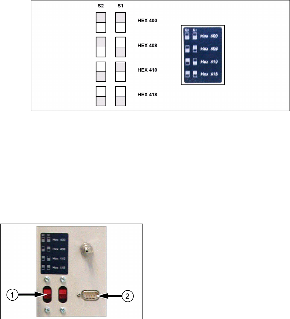
Docking station: CAN bus addresses
► Make sure that you only assign each address once, when setting the CAN Bus address.
Establishing a Data Connection
Establish a data connection between the docking station and the Setup Center PC. This data connection
is realized via a CAN Bus. Ensure that you have already installed the CAN card in your PC.
Connect the CAN cable to the docking station and the PC. This CAN cable has 5 connections, one of
which you can use for the PC. This leaves 4 other connections, allowing you to connect up to 4 docking
stations with this cable.
► Connect the CAN cable to the CAN connection at your docking station. This can be found on the
back of the docking station.
► Connect the CAN cable to the CAN card on the PC (CAN Bus 1 or 2).
Docking Station X
1. CAN Bus Address Switch
2. CAN Connection
Installation
Hardware Installation Optional: Docking Station
44 Installation Manual SIPLACE Setup Center 5.1
See the connection scenarios below for CAN Bus cable connection.
CAN Bus Cable Connection Examples
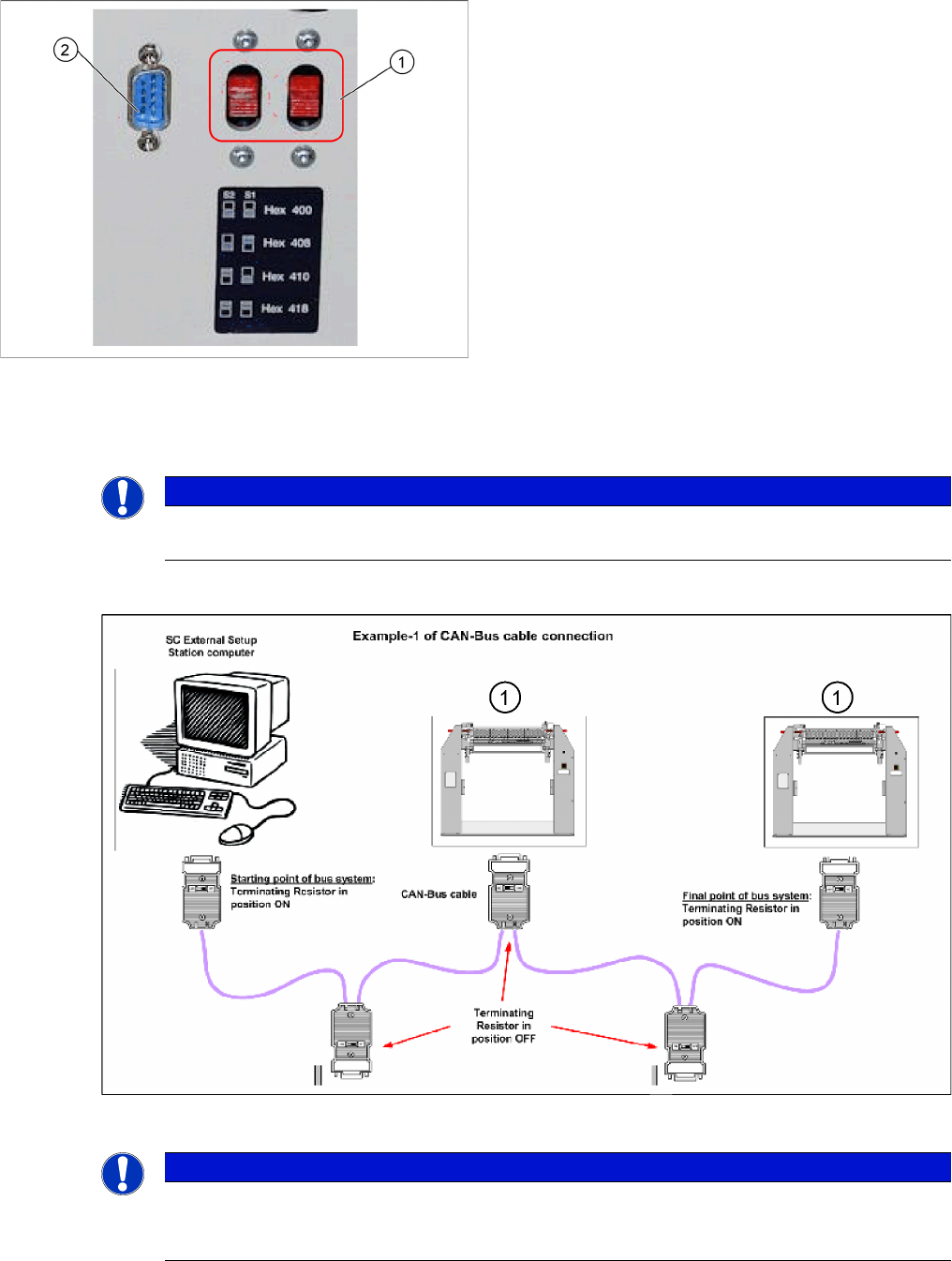
Connection Example 1
1. Docking Station X or SX
Docking Station SX
1. CAN Bus Address Switch
2. CAN Connection
NOTICE
The first and the last terminating resistor must always be switched ON and the other switched
OFF independent of the number of docking stations.
NOTICE
The integrated terminal resistor can be connected and simultaneously connects / disconnects
the outgoing bus cable when deactivating / activating. This allows an easy start up of the bus
system one segment at a time.
Installation
Optional: Docking Station Hardware Installation
Installation Manual SIPLACE Setup Center 5.1 45
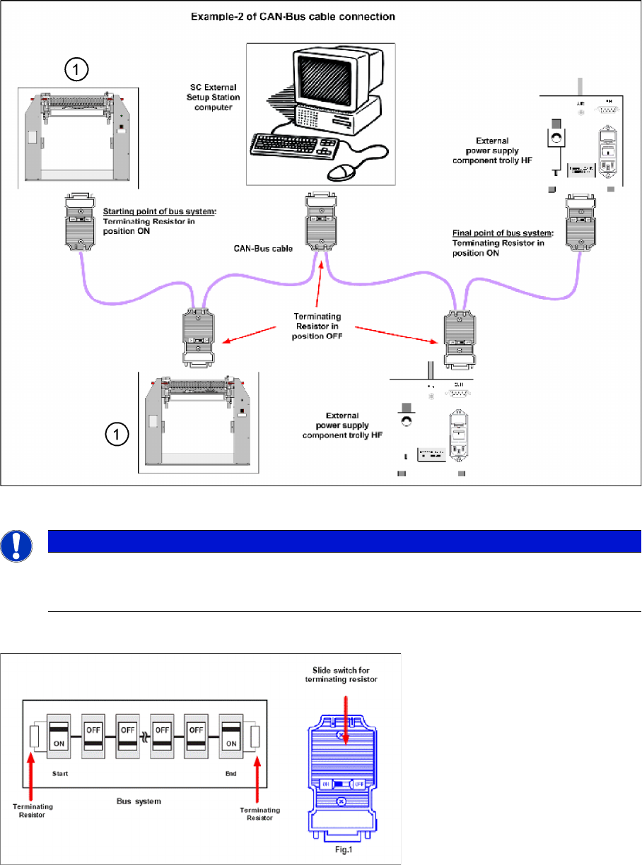
Connection Example 2
1. Docking Station X or SX
Connection Example 1 and 2
NOTICE
The integrated terminal resistor can be connected and simultaneously connects / disconnects
the outgoing bus cable when deactivating / activating. This allows an easy start up of the bus
system one segment at a time.