4OM-996-007.pdf - 第123页
(5) Loosen 3 setscrews fastening the diffusion plate with the 2 mm bit (Standard Accessory Part: 630 1 16 3673) and detach the dif fu- sion plate from the head. Do not apply a wrench, etc., to the mag- net for head origi…
1.4.6 Disassembly, Cleaning, and Lubrication of Miniature Stroke
Bearing
Since the disassembly, cleaning, and lubrication work of the minia-
ture stroke bearings requires highly sophisticated technique, consult
our service personnel for details.
••
••
• Time for Inspection, Cleaning, and Lubrication
Perform inspections every month.
Cleaning and lubrication are required when dirt and dust have accu-
mulated on the sliding part of the shaft and the movement is ham-
pered or on the hollow portion of the shaft and the suction force has
deteriorated.
Be sure to clean the miniature stroke bearing every 6 months.
• Disassembly of Miniature Stroke Bearing
Disassembly Procedure
(1) Set all nozzles to "L Level".
Refer to "4.2.2 "Manual Opn" Tab" in "Section
6 (Volume 2: Operation (Supervisor)" for the
detailed information on how to change the
nozzle level.
(2) Make the X/Y table retreat.
Refer to "4.2.1 "Noz Cleaning" Tab" in "Sec-
tion 6 (Volume 2: Operation (Supervisor)" for
the detailed information on how to make the
X/Y table retreat.
(3) Turn off the power and air sources of the ma-
chine to discharge the air from the machine.
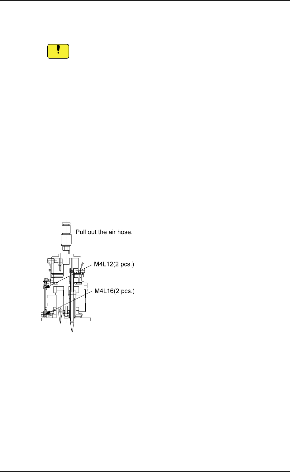
(4) Detachment of Head Assembly
(4-1) Loosen 2 M4L12 bolts (upper ones) and 2
M4L16 bolts (lower ones) fastening the head
and detach the head assembly.
(4-2) Pull out the air hose.
(4-3) Pull the head forward to detach.
Fig. 4A69
1.4 Maintenance Method
0509-003 1-56 AIM01ETRP
Notice
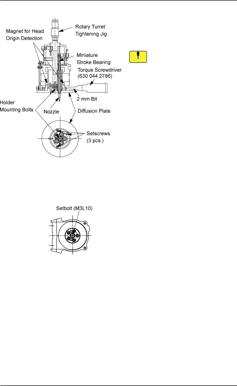
(5) Loosen 3 setscrews fastening the diffusion
plate with the 2 mm bit (Standard Accessory
Part: 630 116 3673) and detach the diffu-
sion plate from the head.
Do not apply a wrench, etc., to the mag-
net for head origin detection.
Otherwise, the magnet will be
demagnetized.
(6) Loosen three setscrews fastening the diffu-
sion plate and detach the plate from the head.
1.4 Maintenance Method
Fig. 4A71
Removal from Head Bottom
Fig. 4A70
0412-002 1-57 AIM01ETRP
Notice
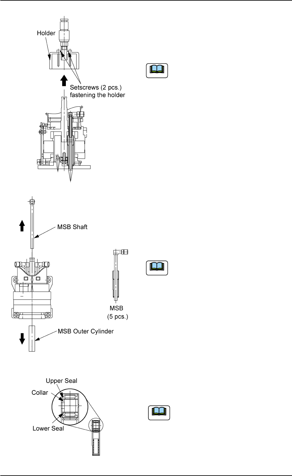
(7) While pressing the holder, loosen 2 setscrews
on the upper area of the head adequately with
the 1.5 mm bit (Standard Accessory Part: 630
116 3673) to detach the holder from the head.
(a) Carefully loosen 2 setscrews be-
cause the holder pops out upward.
(b) To avoid damaging the tapped hole,
use a hexagon wrench (TONE,
BONDUS) that fits the diagonal di-
mensions.
(8) Detach the miniature stroke bearing (MSB).
(8-1) Detach the MSB shaft and outer cylinder.
Pull out the MSB shaft from the upper side.
Use a pair of tweezers to pull out the MSB
outer cylinder from the lower side.
Do not change the combination of the
MSB shaft and the MSB outer cylinder.
Otherwise, the smooth movement of the
head cannot be expected and the head
may have some leeway.
(9) Detach the upper seal, the collar, and the
lower seal from the MSB outer cylinder.
When the upper and lower seals are
scratched or deformed or foreign
substances have accumulated on
them, replace them with new ones
(630 048 0849).
1.4 Maintenance Method
Fig. 4A73
Fig. 4A74
Fig. 4A72
0309-002 1-58 AIM01ETRP
Note
Note
Note