4OM-996-007.pdf - 第131页
1.4.7 Lamp Replacement of Light Source Device for Recognition Lighting (1) Light Source Devices Light Source Devices : #MHF-P100LRD-SO-2 Lamp : LM-100 (2) Lamp Replacement Procedure • T urn off the power switch of the li…
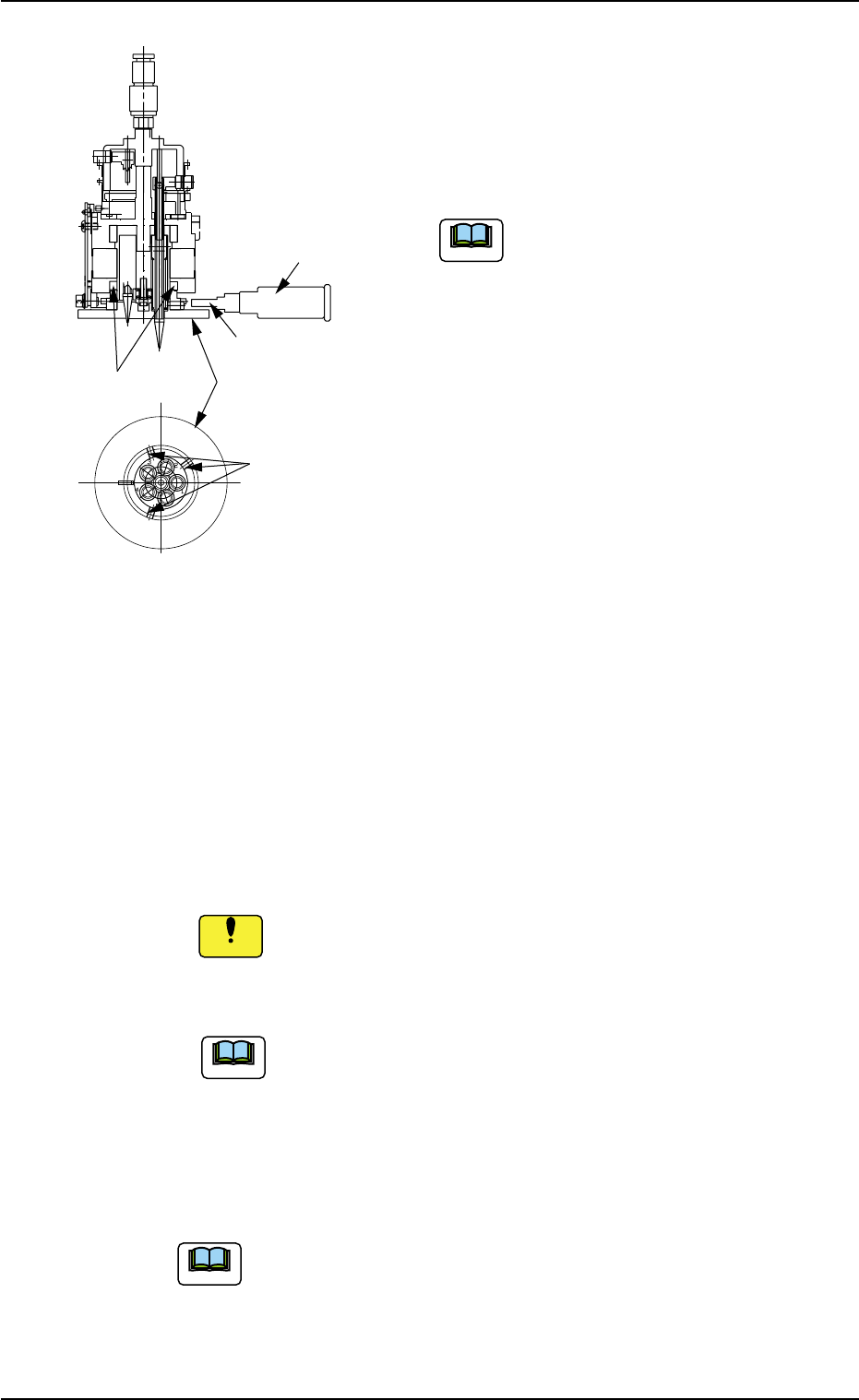
(4) Attach the diffusion plate to the head.
Tighten 3 special anti-loosening screws
(silicon-varnished ones) with a tightening
torque of 10 kgfcm, using the 2 mm bit
(standard accessory part: 630 116 3673).
Do not allow any solvent, alcohol, etc.,
to adhere to the diffusion plate. Other-
wise, the diffusion plate may crack.
(5) Apply "DAPHNE EPONEX GREASE No. 1"
thinly to the cam face of the holder.
(6) Attachment of Head Assembly to Head Assembly Holder
(6-1) Fit the pilot pin hole on the rear side of the head assembly into the
pilot pin on the holder side.
(6-2) Fasten the head assembly, using 2 screws (M4X12) for the up-
per face and 2 screws (M4X16) for the lower face.
(Tightening Torque: Approx. 44 kgfcm)
Do not make a mistake in selecting the length of screws. Other-
wise, the screw thread of the head will be damaged.
(6-3) Insert the hose.
Do not apply a wrench, etc., to the magnet for head origin
detection. Otherwise, the magnet will be demagnetized.
If the magnet is demagnetized, the origin may not be de-
tected.
(7) Perform the "Head/Nozzle" and the "Head Origin" offset teaching
operations on the attached nozzle.
Refer to "5.1 "Head/Nozzle" Tab" and "5.2 "Head Origin"
Tab" in "Section 6" of "Vol. 2: Operation (Supervisor)" for
the offset teaching operations.
• The head origin offset must be ±3 degrees or less.
• The head center offset must be ±3 mm or less.
1.4 Maintenance Method
Fig. 4A82
Note
0509-003 1-64 AIM01ETRP
Setscrews
(3 pcs.)
Magnet for Head
Origin Detection
Diffusion Plate
2 mm Bit
Torque Screwdriver
(630 044 2786)
Note
Note
Notice
1.4.7 Lamp Replacement of Light Source Device for Recognition
Lighting
(1) Light Source Devices
Light Source Devices : #MHF-P100LRD-SO-2
Lamp : LM-100
(2) Lamp Replacement Procedure
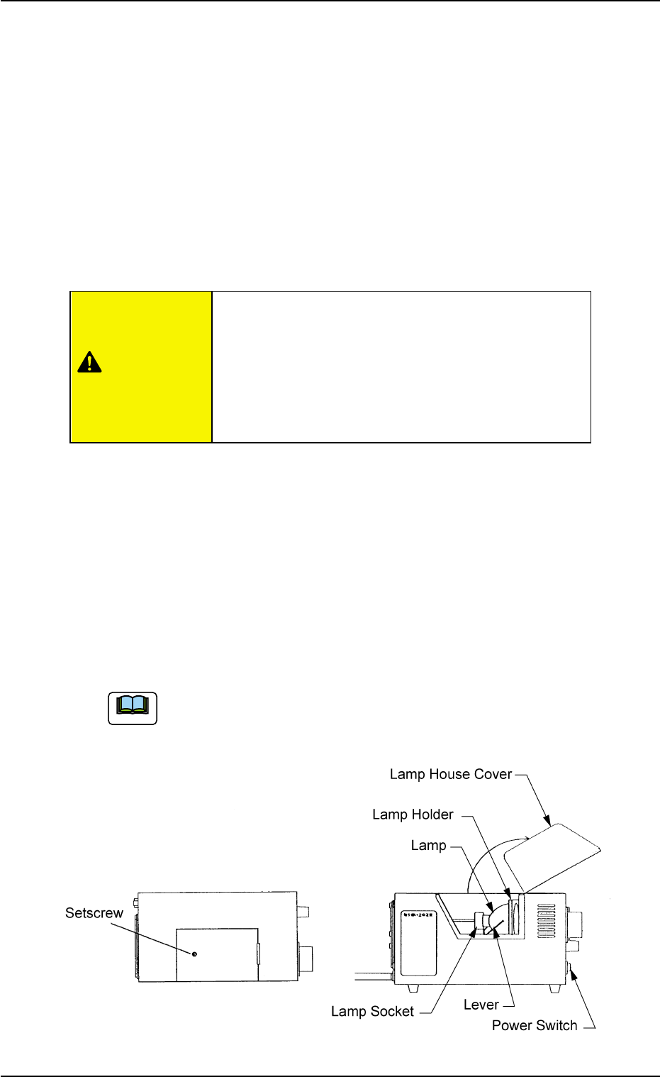
• Turn off the power switch of the light source device and check that
the LED (Orange) of the power switch extinguishes.
• Loosen the setscrew on the main body of the light source device and
open the lamp house cover.
• Lift the lever located on the left side of the lamp in the arrow direction.
The lamp will also be lifted up.
• Pull out the lamp straight up from the lamp holder.
• Detach the lamp from the socket.
When the lamp is inserted or pulled out, be sure not to forcibly
screw the terminal into or unscrew it from the socket. Other-
wise, the socket may be damaged.
Fig. 4A83
Do not touch the lamp right after it has been turned
off because it is very hot. Wait for about 3 to 5
minutes or until it cools down.
Be sure to wear gloves made of thick material (for
example, cotton work gloves) to replace the lamp
right after it has been turned off.
1.4 Maintenance Method
0509-003 1-65 AIM01ETRP
CAUTION
Note
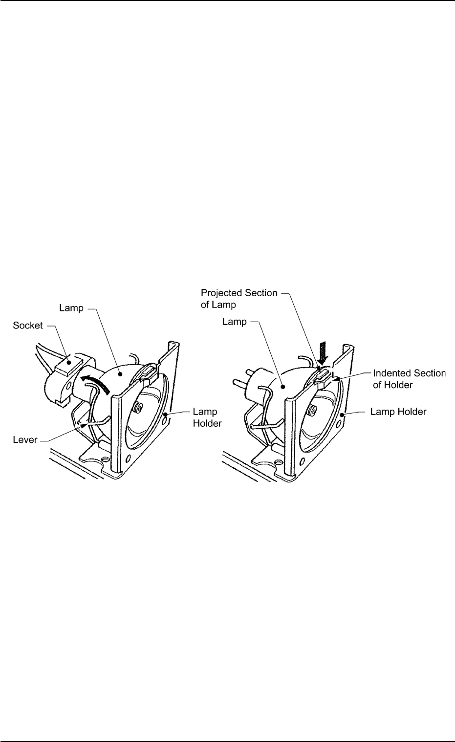
• Return the lever to the original position.
• Put a new lamp in the lamp socket and push it down until it reaches
the bottom of the lamp holder. At this time, direct the side of the lamp
where the projected section is located so that the projection matches
the indented section of the lamp holder.
• Close the lamp house cover and shift down the lock lever to fasten
the cover.
• Turn on the power switch of the light source device and check that
the LED (orange) of the power switch illuminates.
• The lamp replacement is completed.
Perform lighting check operation after lamp replacement.
Fig. 4A83-1
1.4 Maintenance Method
0305-001 1-66 AIM01ETRP