4OM-996-007.pdf - 第133页
1.4.8 Replacement of Cutter Blade Time of Replacement Replace a cutter blade with a new one when the cutting quality has deteriorated due to wear , cracks, etc. Replacement Procedure (1) Zero the feeder carriage and turn…
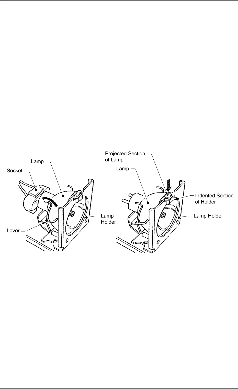
• Return the lever to the original position.
• Put a new lamp in the lamp socket and push it down until it reaches
the bottom of the lamp holder. At this time, direct the side of the lamp
where the projected section is located so that the projection matches
the indented section of the lamp holder.
• Close the lamp house cover and shift down the lock lever to fasten
the cover.
• Turn on the power switch of the light source device and check that
the LED (orange) of the power switch illuminates.
• The lamp replacement is completed.
Perform lighting check operation after lamp replacement.
Fig. 4A83-1
1.4 Maintenance Method
0305-001 1-66 AIM01ETRP
1.4.8 Replacement of Cutter Blade
Time of Replacement
Replace a cutter blade with a new one when the cutting quality has
deteriorated due to wear, cracks, etc.
Replacement Procedure
(1) Zero the feeder carriage and turn off the power supply.
Set the angle of the rotary turret to 108° (origin) to prevent
interference between the lower and upper blades.
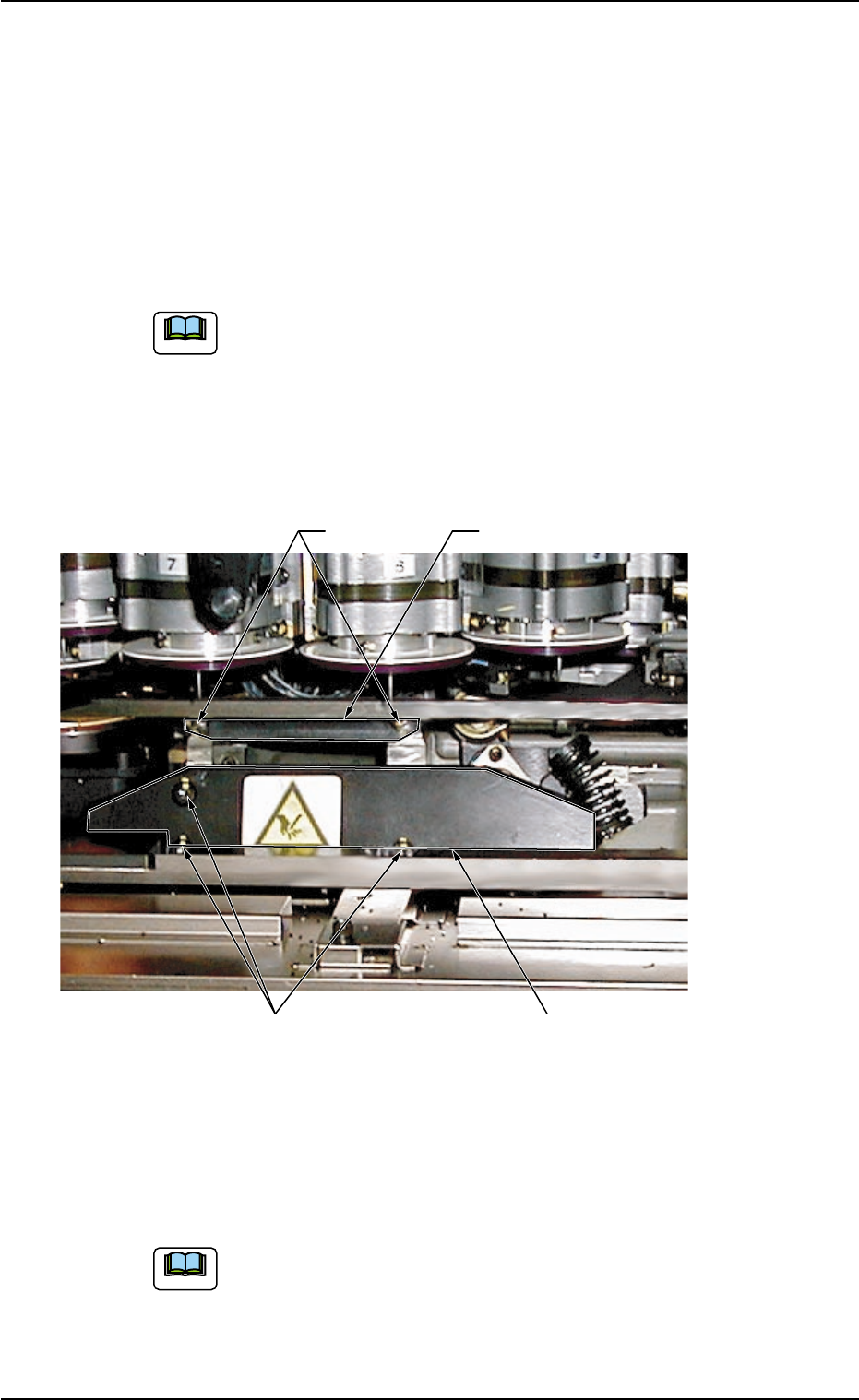
(2) Open the central safety guard of the feeder unit.
(3) Detach the upper blade by removing Bolts A (M5 × 16).
Fig. 4A84
(4) Remove Bolts B (M5 × 12) fastening the lower blade holding plate
with the torque L-type wrench (Standard Accessory Part: 630 063
9759) and detach the plate.
While detaching the lower blade holding plate, be careful not
to touch the nozzles and diffusion plates. Also, avoid hitting
them with a tool.
1.4 Maintenance Method
Upper Blade
Lower Blade Holding Plate
Bolts A
Bolts B
0509-005 1-67 AIM01ETRP
Note
Note
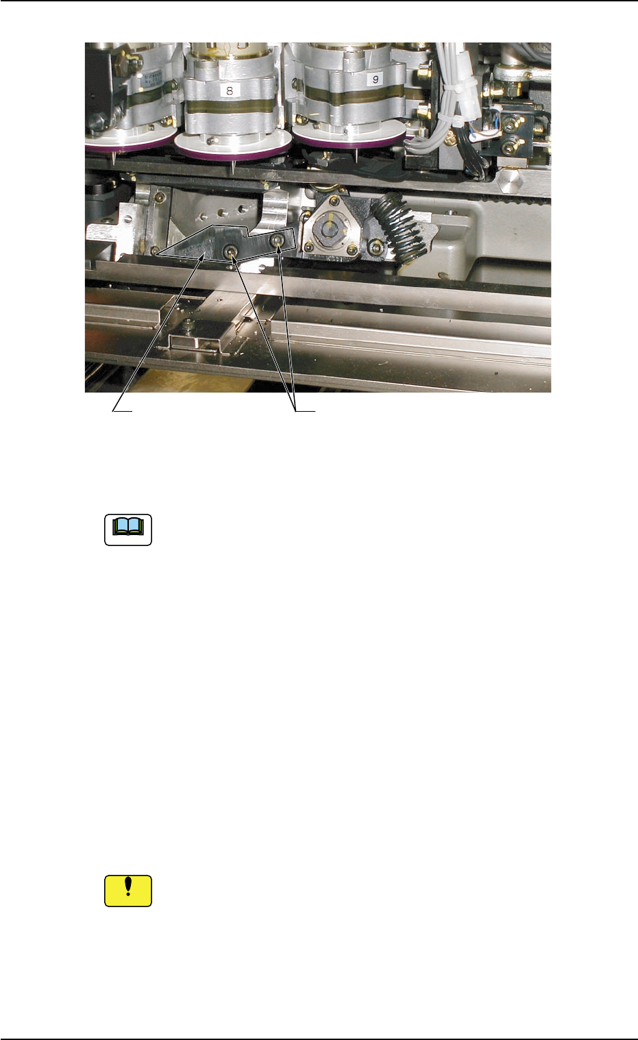
Fig. 4A84-1
(5) Detach the lower blade by removing Bolts C (M5 × 12).
When the lower blade cannot be detached easily, try to pull it
right and left alternately.
(6) Attach a new lower blade and secure it with Bolts C (M5 × 12).
(7) Attach the new lower blade holding plate and secure it with Bolts B
(M5 × 12).
(8) Attach a new upper blade and secure it with Bolts A (M5 × 16).
(9) Close the central safety guard of the feeder unit.
(10) Turn on the power supply of machine and confirm that the rotary
turret works normally, using "Smooth Manual Axis Operation (Low
Speed)" for the rotary turret.
Before operation, be sure to confirm that the lower blade holding
plate is securely attached.
Refer to "2.2.1 "Rotary Turret" Tab" in "Section 6 (Vol. 2)" for details.
1.4 Maintenance Method
Lower Blade Bolts C
Note
0509-006 1-68 AIM01ETRP
Notice