4OM-996-007.pdf - 第311页
(44 Self-Diagnostics 2) Error ID ltem Description 440101 Cam Phase Gap of cam phase has been detected. (Cause 1) Self-Diagnostics Error Message (Remedy 1) Zero all axes and re-start the operation. When the machine cannot…
Error ID ltem Description
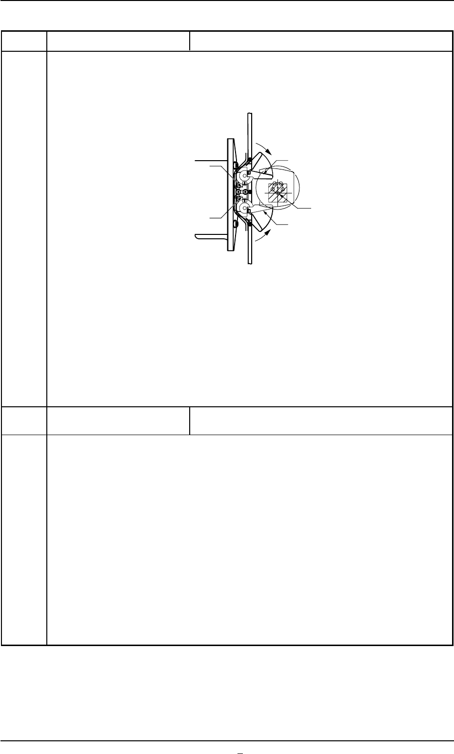
(4) Open the central safety door (feeder carriage cover) and return the pickup error check
plate to the original detectable position.
• Return the pickup error check plate to the position where it is aligned parallel to the
tape feed direction of the tape feeder.
Fig. 4B21-2
(5) Cancel the "Emergency Stop" mode.
Refer to "3.1 [EMERGENCY STOP] Switch Pressed" in "Section 4" (Vol. 1) for how
to reset the [EMERGENCY STOP] switch to its normal condition.
431001 Inverter Inverter alarm signal was detected.
[Shutdown touch sw key and mainbreaker sw off.]
(Cause 1) When an instantaneous power failure occurs in the power supply to the machine, the
machine is stopped in an error condition.
(Remedy 1) (1) Reset the error window, follow the shutdown procedure, and set the power
breaker to "OFF".
(2) Wait for approximately 10 seconds. Then, set the power breaker to "ON" to
start up the machine.
(3) Perform the zeroing operation and restart the operation.
* When a P.C.B was produced at the time of error, follow the "Warm Start"
procedure and finish the P.C.B.
(Remedy 2) When an error still occurs after shutdown and power breaker reset operations and
the machine cannot be reset to its normal condition because there is a problem in
the power supply line, consult our service personnel for the remedy.
0509-001 2-116-1 AIM01ETRP
3.3 Error IDs and Remedial Procedures
Pickup Error Check Sensor A
Pickup Error Check Sensor B
Return
Return
Pickup Error Check Plate A
Pickup Center
Pickup Error Check Plate B

(44 Self-Diagnostics 2)
Error ID ltem Description
440101 Cam Phase Gap of cam phase has been detected.
(Cause 1) Self-Diagnostics Error Message
(Remedy 1) Zero all axes and re-start the operation.
When the machine cannot be set to its normal condition, consult our service
personnel for the remedy.
440201 The Comp. Placement Lever The structure of comp. placement lever was not activated.
;BPH28 E/NR
440202 The Comp. Placement Lever The comp. placement lever moves despite being held by stop-
per.
440203 The Comp. Placement Lever The comp. placement lever does not move even though stop-
per was open.
(Cause 1) The sensor is defective or is not adjusted to the correct position.
The sensor does not turn ON or OFF due to adhered dirt.
(Remedy 1) Wipe off dirt on the sensor and zero all axes again.
440301 The Comp. Pick-Up Lever The structure of comp. pick-up lever was not activated.
;BPH29 E/NR
440302 The Comp. Pick-Up Lever The comp. pick-up lever moves despite being held by stop-
per.
440303 The Comp. Pick-Up Lever The comp. pick-up lever does not move even though stopper
was open.
(Cause 1) The sensor is defective or is not adjusted to the correct position.
The sensor does not turn ON or OFF due to adhered dirt.
(Remedy 1) Wipe off dirt on the sensor and zero all axes again.
440401 The Feeder Index Lever #2 The structure of feeder index lever was not activated.
;BPH31 E/NR
(Cause 1) An optical beam of the sensor is always kept in the "E/NR" or the "E/R” condition.
(ENR: Light Emitted and Not Received, E/R: Light Emitted and Received)
(Remedy 1) Press the [RETURN] button to cancel the error display and check if the optical
beam of the sensor is set in the "E/NR” or the "E/R" condition.
• Cover the optical beam of the sensor with a piece of paper to see if the optical
beam can be shielded or received and check the reaction.
• If necessary, wipe off dirt on the sensor and then perform the zeroing operation
on all axes.
Note: Never detach the sensor. Otherwise, the optical axis will shift, causing
the timing to drift.
Whenever the sensor was detached, consult our service personnel for
the attachment.
0509-003 2-117 AIM01ETRP
3.3 Error IDs and Remedial Procedures

Error ID ltem Description
440402 The Feeder Index Lever #2 The feeder index lever moves despite being held by stopper.
(Cause 1) The optical beam of the sensor was shielded.In normal cases, the sensor must be in
the "E/R" mode. (E/R: Light Emitted and Received)
(Remedy 1) Press the [RETURN] button to cancel the error display and check that the optical
beam of the sensor is in the "E/NR" mode. (E/NR: Light Emitted and Not Re-
ceived)
• Cover the optical beam of the sensor with a piece of paper to see if the optical
beam can be shielded or received and check the reaction.
• If necessary, wipe off dirt on the sensor and then perform the zeroing operation
on all axes.
Note: Never detach the sensor. Otherwise, the optical axis will shift, causing
the timing to drift.
Whenever the sensor was detached, consult our service personnel for
the attachment.
440403 The Feeder Index Lever #2 The feeder index lever does not move even though stopper
was open.
(Cause 1) The optical beam of the sensor was received. In normal cases, the sensor must be in
the "E/NR” mode. (E/NR: Light Emitted and Not Received)
(Remedy 1) Press the [RETURN] button to cancel the error display and check that the optical
beam of the sensor is in the "E/NR” mode. (E/NR: Light Emitted and Not Re-
ceived)
• Cover the optical beam of the sensor with a piece of paper to see if the optical
beam can be shielded or received and check the reaction.
• If necessary, wipe off dirt on the sensor and then perform the zeroing operation
on all axes.
Note: Never detach the sensor. Otherwise, the optical axis will shift, causing
the timing to drift.
Whenever the sensor was detached, consult our service personnel for
the attachment.
440501 The Feeder Adhesive Tape The structure of feeder adhesive tape lever was not activated.
(Cause 1) An error was found in the adhesive tape take-up mechanism.
(Cause 2) Self-Diagnostics Error Message.
(Remedy 1) When dirt adheres to the sensor, wipe it off.
When an error is found in the adhesive tape take-up mechanism, consult our
service personnel for the remedy.
(Remedy 2) Zero all axes and re-start the operation.
When the machine cannot be set to its normal condition, consult our service
personnel for the remedy.
0305-001 2-118 AIM01ETRP
3.3 Error IDs and Remedial Procedures