4OM-996-007.pdf - 第70页
Nozzle for Dispense Gun DG10KIT T able 4A7 Standard Shape Part No. Remarks No.14 1 0 1 2 630 062 2591 (Color: Olive) No.18 1 0 0 1 630 062 2607 (Color: Green) No.19 0 1 1 2 630 062 2621 (Color: Brown) No.20 1 0 0 2 630 0…
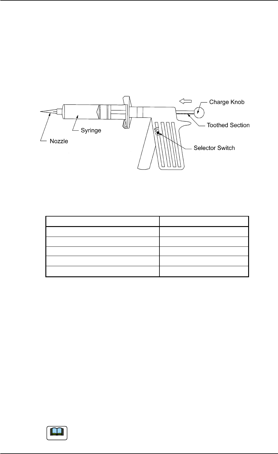
(6) Dispense Gun "DG10KIT"
Maker: Sanei Tech
This gun can be used for three types of greases.
Use the syringes and the nozzles properly.
Three Types of Greases: DAPHNE EPONEX GREASE No. 1
DAPHNE EPONEX GREASE No. 3
NEW MOLYNOC GREASE No. 1
Appearance
Fig. 4A4
<Contents of Kit>
Table 4A6
Part Name Q’ty
Dispense Gun (Main Body) for 10 cc 1
Syringe 20
Piston 20
End Cap 20
Syringe Cap 20
Usage
(6-1) Set the selector switch to "1" in normal cases.
Note: When the switch is set to "2", grease will be pushed out
excessively.
Be sure to set the switch to "R" before storing the gun (keeping it
unused).
(6-2) Before the charge knob is pushed to dispense the grease, con-
firm that the charge rod is inserted with its toothed section facing
downward.
(6-3) Check the amount of grease before it is supplied
(6-4) Push the charge knob slightly forward before the grease is sup-
plied.
Refer to the attached instruction manual for the detailed infor-
mation on how to use the dispense gun.
1.2 Preparation for Maintenance
0305-001 1-6 AIM01ETRP
Note
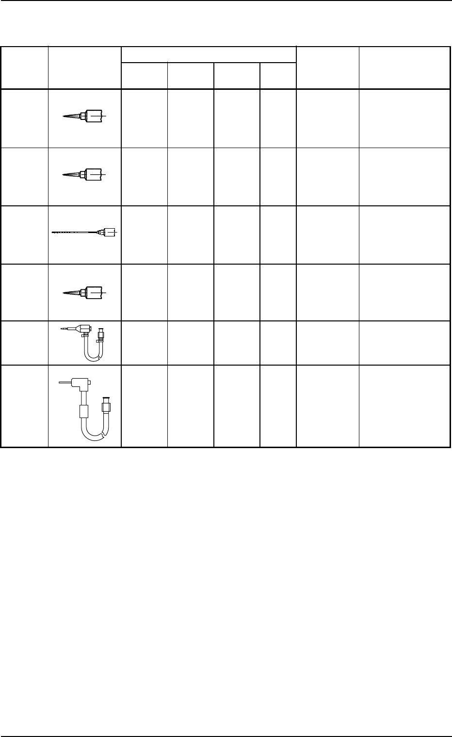
Nozzle for Dispense Gun DG10KIT
Table 4A7
Standard Shape Part No. Remarks
No.14 1 0 1 2 630 062 2591
(Color:
Olive)
No.18 1 0 0 1 630 062 2607
(Color:
Green)
No.19 0 1 1 2 630 062 2621
(Color:
Brown)
No.20 1 0 0 2 630 062 2614
(Color:
Pink)
HL2 Type 0 1 0 1 630 105 4445
RR Type 0 1 0 1 630 110 5307
Grease and Number of Required Nozzles
For DAPHNE
EPONEX
GREASE No. 1
For NEW
MOLYNOC
GREASE No. 1
Total
Frequency
in Use
For DAPHNE
EPONEX
GREASE No. 3
Maker: Sanei Tech
Inside Diameter: φ1.6
Tapered Nozzle
#5114TT-B
Maker: Sanei Tech
Inside Diameter: φ0.84
Tapered Nozzle
#5118TT-B
Maker: Nipro
Inside Diameter: φ0.79
Length: 65 mm
Flattened End
Maker: Sanei Tech
Inside Diameter: φ0.58
Tapered Nozzle
#5120TT-B
Maker: HTI
Maker: HTI
1.2 Preparation for Maintenance
0305-001 1-7 AIM01ETRP
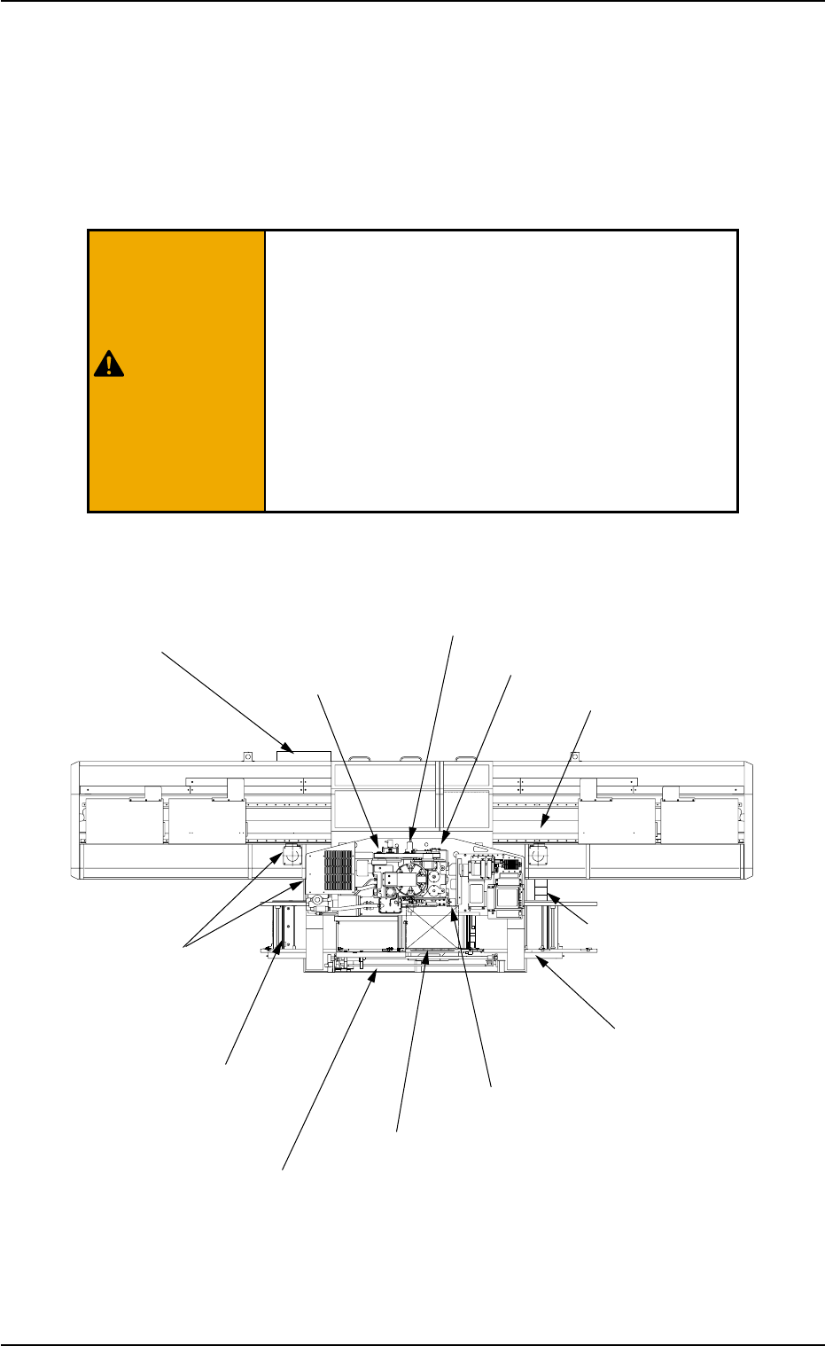
1.3 Maintenance Spots
1.3.1 General View
Refer to "1.3.2 Inspection, Cleaning, and Lubrication Spots" and after
for details.
Fig. 4A5 Top View of Machine
1.3 Maintenance Spots
(17) P.C.B. Transfer Section
(8) Light Source Device for
Component Recognition
(27) L/R Conveyor Sections
(26) Filters and
Fans in Each Section
(2) Vacuum System
(3) Dust Collector and
Waste Tape Box
(7) X/Y Table Section
(20) Placement Height Correction Section
(13) Feeder Carriage
Section
(22) Tape Feed Unit Section
(5) Intermediate Base
(18) Pick-Up Height
Correction Section
(28) Exhaust Cleaner
• Before performing maintenance work, turn off the
power and air sources and lock the power breaker
using the padlock.
• Designate a person who can have charge of the
padlock key.
• The cover of the machine must be detached for
the maintenance work.
After the maintenance work, be sure to attach the
cover.
0412-004 1-8 AIM01ETRP
WARNING