P-0295-004.pdf - 第112页
0801-002 53 54 55 53 34 32 33 31 34 33 32 54 61 . 71 . 75 55 55 55 31 31 34 32 31 34 32 33 81 . 91 . 92 61 . 71 . 75 61 . 71 . 75 61 . 71 . 75 81 . 91 . 92 81 . 91 . 92 34 32 33 31 34 33 32 31 内が本体対応箇所です。 The explanation…
0801-002
G -S014-12,13,14,15 G -S014-12,13,14,15
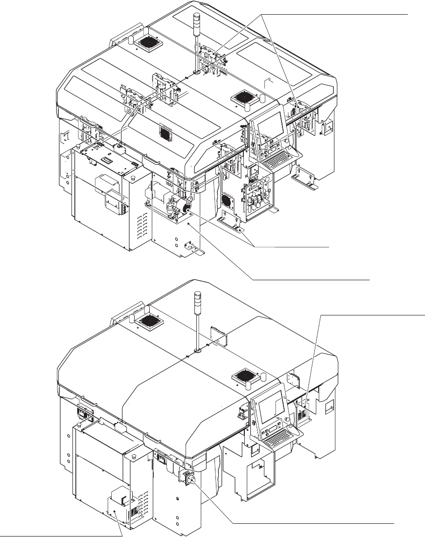
多段トレイ取付本体対応
Main Machine Modification For
Attaching Multi-Layer Tray Feeder
注)
イラストはGXH本体に多段トレイを装着した場合の、本体対応箇所
を示しております。
本体部Fig.B
MAIN BODY SECTION
カバー部Fig.G COVER SECTION
位置決め部Fig.J
POSITIONING SECTION
架台上全体部準備Fig.DX
OVERALL UPPERFRAME PREPARATION SECTION
Notice)The illustration shows the locations to be treated in the main unit when the
Multi-Layer Tray Feeder is mounted onto the GXH Main Machine.
Fig.FB 制御PC部 左
CONTROL PC SECTION LEFT
Fig.FD 制御PC部 右
CONTROL PC SECTION RIGHT
UNIT
0801-002
53
54
55
53
34
32
33
31
34
33
32
54
61
.
71
.
75
55
55
55
31
31
34
32
31
34
32
33
81
.
91
.
92
61
.
71
.
75
61
.
71
.
75
61
.
71
.
75
81
.
91
.
92
81
.
91
.
92
34
32
33
31
34
33
32
31
内が本体対応箇所です。
The explanation in brackets is
for the locations to be treated
in the main machine.
Delete
B-1 illust-1
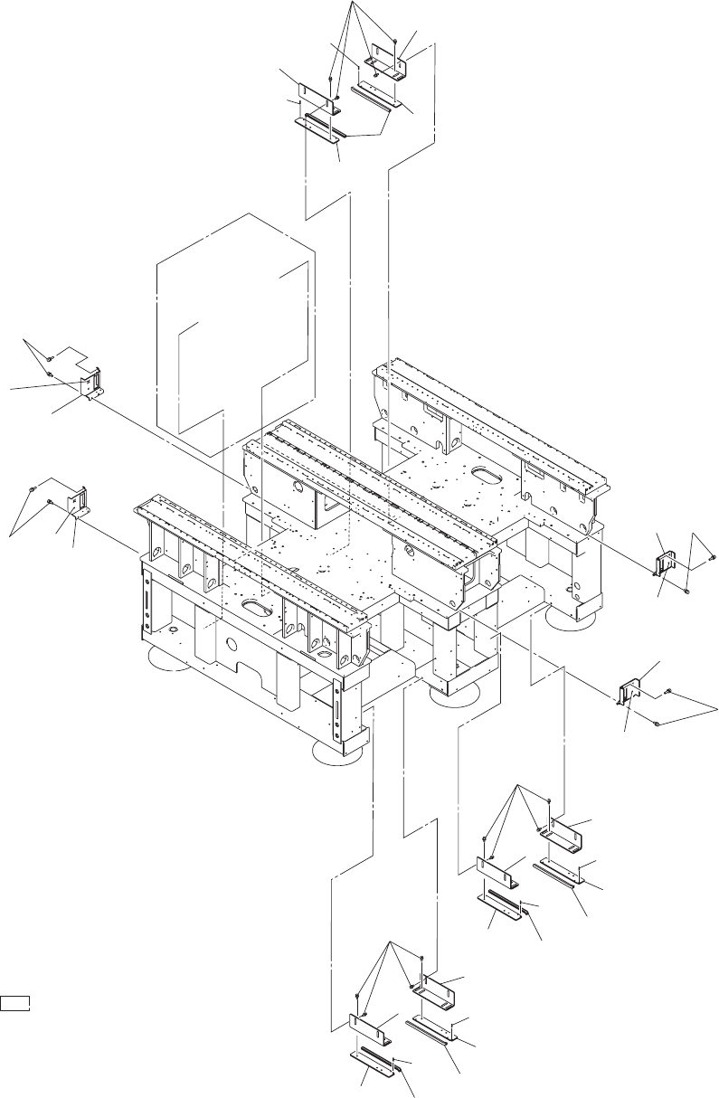
本体部
MAIN BODY
SECTION
Fig. B-1
カートガイド
(G -S014-12)
Cart Guide(G -S014-12)
0801-002
53
54
55
53
54
61
.
71
.
75
55
55
55
31
34
32
31
34
32
33
81
.
91
.
92
31
34
32
31
34
32
33
81
.
91
.
92
61
.
71
.
75
61
.
71
.
75
61
.
71
.
75
81
.
91
.
92
34
32
33
31
34
33
32
31
内が本体対応箇所です。
The explanation in brackets is
for the locations to be treated
in the main machine.
Delete
B-1 illust-2
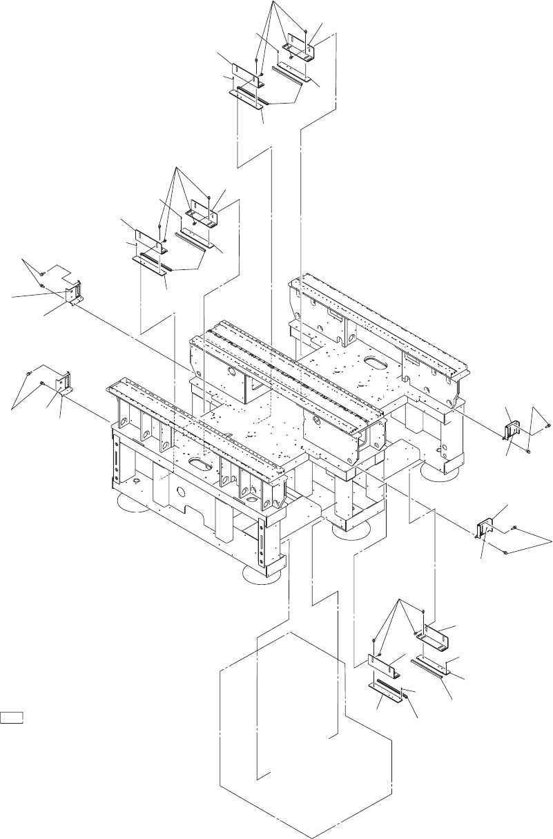
本体部
MAIN BODY
SECTION
Fig. B-1
カートガイド
(G -S014-13)
Cart Guide(G -S014-13)