4OM-1505-004_w.pdf - 第94页
4OM-1505 1-43 4. Maintenance Method : Chap.1 4.1.3 Replacement Procedure of Blower Filter Procedure (1) Remove the cover on the front lower section and lift the shutter . Disengage the clips fastening the lid of the lte…
4OM-1505
1-42
4. Maintenance Method : Chap.1
(2) Adjust the pushing distance by changing Dimension L (the distance between
the upper end plane of the ball bushing and the lower end plane of the
stopper nut).
(3) Use the "Print Block" window to push the squeegees against the PCB located
at the printing position. (Operation Sequence: [MAINT.] Button → [MAN.
SUB-SYS] Button → "Print Block" Tab)
Refer to the T4A12 and check the relation between Dimension L and the
pushing distances.
(4) Fasten the set screw for the stopper nut.
Note
The pushing distance of the squeegee against the stencil is set to "1.0 mm".
(Factory-Adjusted upon Shipment)
When the stopper nut is turned once clockwise, the pushing distance becomes
shorter by 1.0 mm. Turning the stopper nut once counterclockwise makes the
pushing distance longer by 1.0 mm.
Pushing Distances Dimension L during Upward
Movement of Cylinder
0.5 mm 57.0 mm
1.0 mm 57.5 mm (Standard Setting)
1.5 mm 58.0 mm
T4A12
1002-002
4OM-1505
1-43
4. Maintenance Method : Chap.1
4.1.3 Replacement Procedure of Blower Filter
Procedure
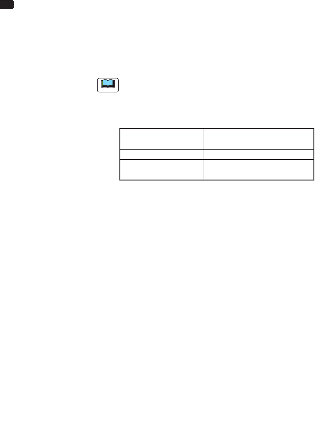
(1) Remove the cover on the front lower section and lift the shutter.
Disengage the clips fastening the lid of the lter cover. (4 places)
Clip
F4A35
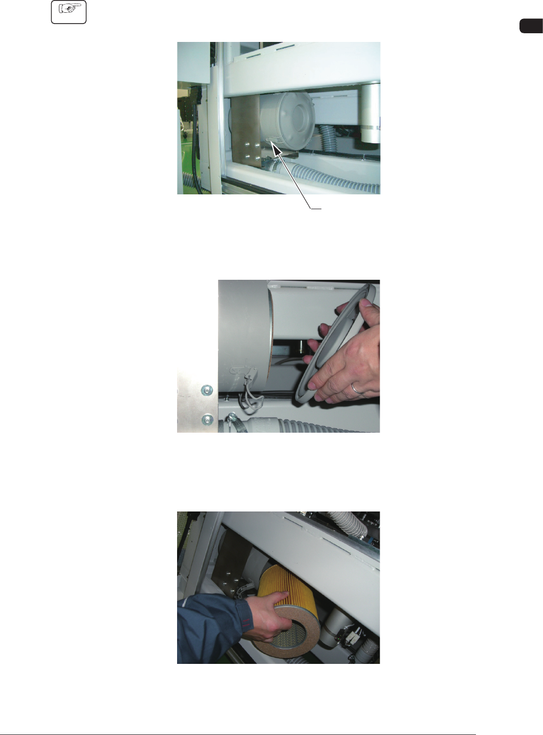
(2) Remove the lid.
F4A36
(3) Detach the lter and remove dust accumulated on the lter with an air gun or
a vacuum cleaner.
F4A37
1002-002
4OM-1505
1-44
4. Maintenance Method : Chap.1
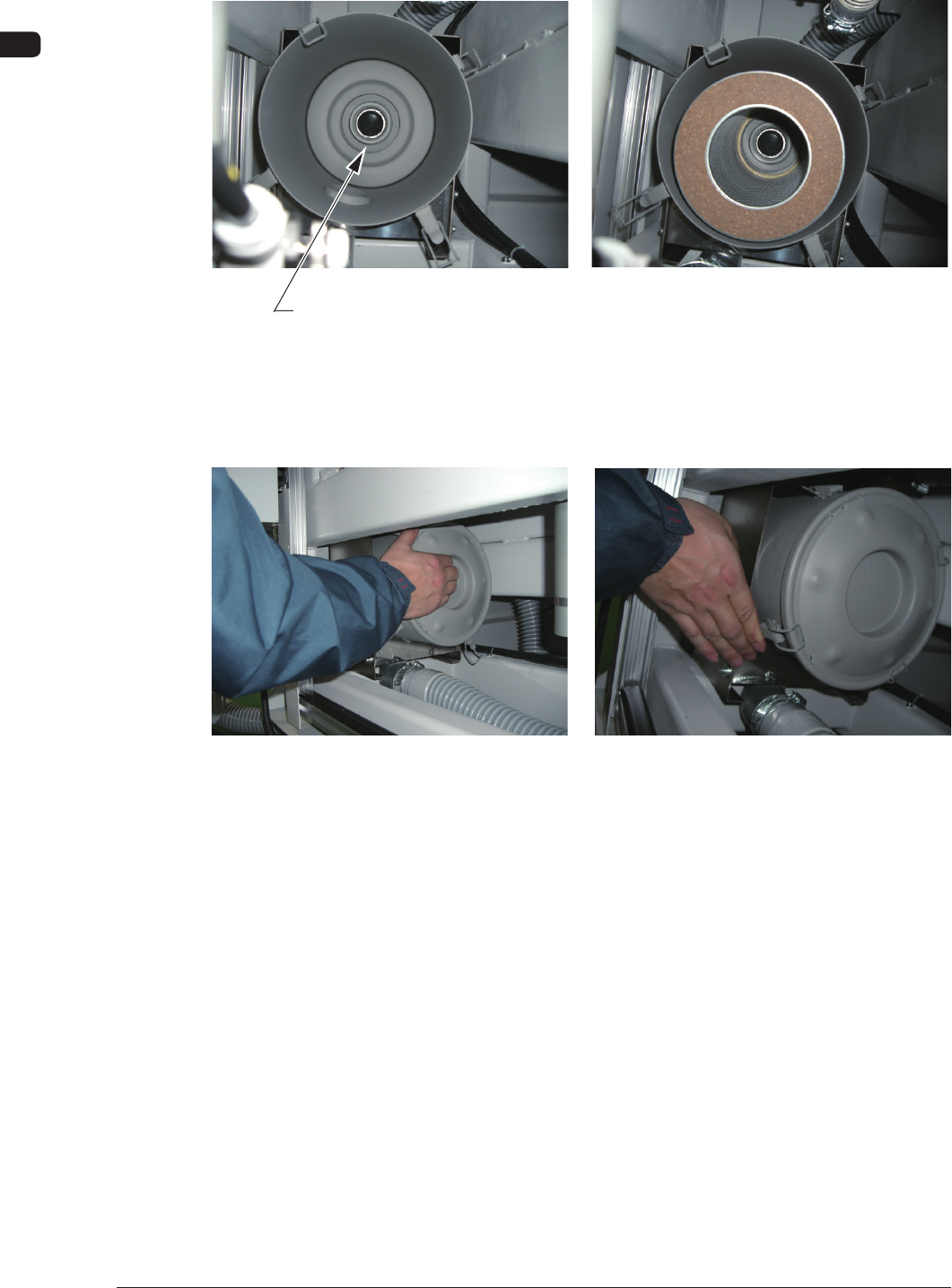
(4) Set the lter such that the center hole of the lter can t into the ange
located at the rear side of the lter cover.
Flange Section
F4A38
(5) While holding the lid, engage the clip securely such that the ange (located
at the center of the lid) can t into the center hole of the lter.
F4A39
0906-001