4OM-1505-004_w.pdf - 第95页
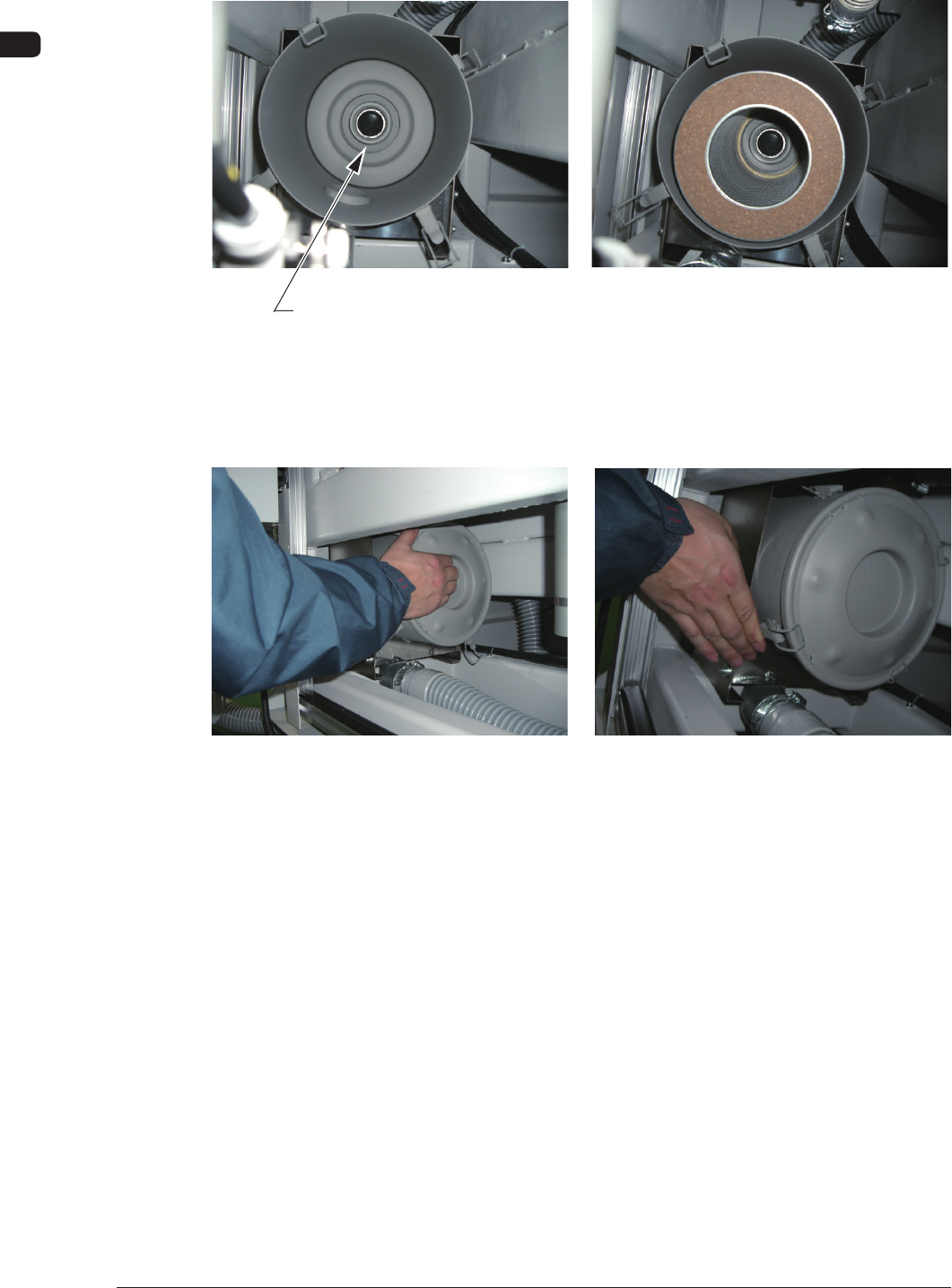
4OM-1505 1-44 4. Maintenance Method : Chap.1 (4) Set the lter such that the center hole of the lter can t into the ange located at the rear side of the lter cover . Flange Section F4A38 (5) While holding the lid, en…
4OM-1505
1-43
4. Maintenance Method : Chap.1
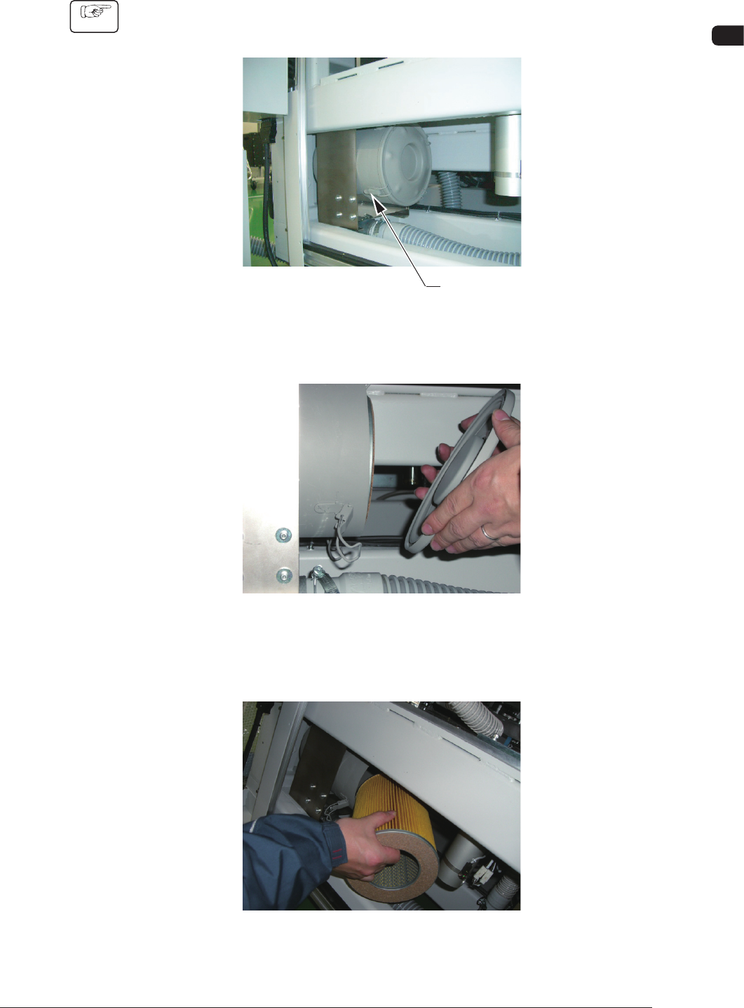
4.1.3 Replacement Procedure of Blower Filter
Procedure
(1) Remove the cover on the front lower section and lift the shutter.
Disengage the clips fastening the lid of the lter cover. (4 places)
Clip
F4A35
(2) Remove the lid.
F4A36
(3) Detach the lter and remove dust accumulated on the lter with an air gun or
a vacuum cleaner.
F4A37
1002-002
4OM-1505
1-44
4. Maintenance Method : Chap.1
(4) Set the lter such that the center hole of the lter can t into the ange
located at the rear side of the lter cover.
Flange Section
F4A38
(5) While holding the lid, engage the clip securely such that the ange (located
at the center of the lid) can t into the center hole of the lter.
F4A39
0906-001
4OM-1505
1-45
4. Maintenance Method : Chap.1
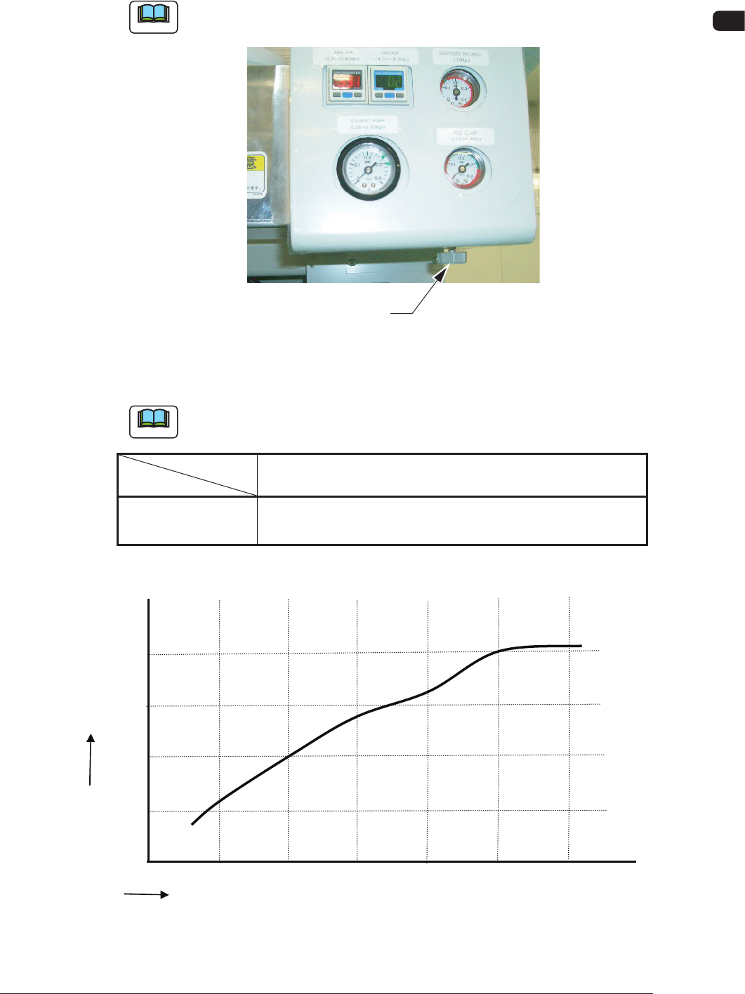
4.2 Adjustment of PCB Horizontal Clamping
The PCB clamp adjustment is performed using the pressure reducing valve.
Note
Perform the adjustment of the pressure reducing value appropriately depending
on the change in the PCB thickness.
Pressure Reducing Valve
F4A40
•
Target Air Pressures Related to PCB Thickness
Example
: The values were obtained when the PCB size is "150 × 100".
Note
Refer to the following table for the standard for the air pressure based on the
PCB thickness.
PCB Thickness
Air Pressure
0.3 0.5 1.0 1.5 2.0 2.5 (mm)
MPa 0.1 0.12 0.2 0.3 0.3 0.4
(kgf/cm
2
) (1.0) (1.2) (2.0) (3.0) (3.0) (4.0)
T4A13
Relationship between the PCB Thickness and Clamp Pressure
Air
Pressure
MPA
PCB Thickness
mm
0.5 1.0 1.5
2.0
0.1
0.2
0.3
0.4
★
★
★
★
0.0
0.3
2.5
3.0
★
★
F4A40-1
1105-002