xp141-241-341-5.0E.pdf - 第103页
FK-9F98- 29 XP Series Training Text for Service Engineers Edition 5.0 XP241 – Chapter 2 Zero Setting Page 3 of 4 Fuji Machine Mfg. Co., Ltd. Okazaki. SMT Equipment Quality Assurance Dept . 2 – 3 CS Section 10. Press [DOW…
FK-9F98-29 XP Series Training Text for Service Engineers
Edition 5.0 XP241 – Chapter 2 Zero Setting Page 2 of 4
Fuji Machine Mfg. Co., Ltd. Okazaki.
SMT Equipment Quality Assurance Dept.
2 – 2 CS Section
2.4 Setting the Servo Amplifier Defaults
1. Set each of the axes to their mechanical stoppers on the minus side. (Please refer to the
mechanical stopper location diagrams in the back of this manual.)
Note: there is NO Minus (-) mechanical stopper on the Q-axis, so set the reference
position where the spline shaft bearing retainer bolt faces out towards the front of the
machine.
Note: cut the servo (200V) when setting each of the
axes to the Minus (-) mechanical stopper.
Note: be careful when using the [JOG] key to set the
T-axis to the Minus (-) mechanical stopper position.
To prevent the T-axis from crashing avoid jogging the
T-axis when in close proximity to the Minus (-)
mechanical stopper.
2. Press the emergency stop button so that the 200v
power supply cuts out.
3. Connect the digital operator to the target servo amp.
(“bb” is displayed on the screen).
4. Press [DSPL/SET] to select the channel mode
(Fn000).
5. Select channel (Fn008) by pressing the [UP] key.
6. Press [DATA/ENTER] to display “PGCL1”.
7. Press [UP] to set it to “PGCL5”.
8. Press [DSPL/SET] and “done” displays.
9. Press [DATA/ENTER] to return to the support mode (Fn008).
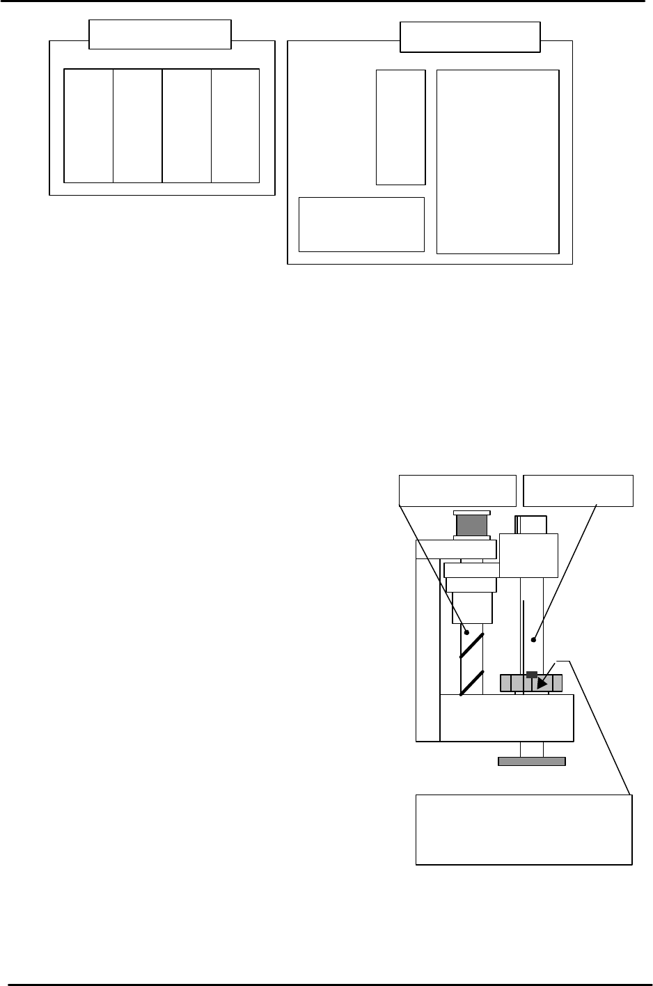
Servo box (rear)
T-axis servo amp
U-axis servo amp
Q-axis servo amp
Z-axis servo amp
Y-axis servo amp.
X-axis servo amp.
Strobe Power
supply
Servo box (front)
Spline shaftZ-axis ball screw
The reference position is where
the spline shaft bearing retainer
bolt faces the M/C front.

FK-9F98-29 XP Series Training Text for Service Engineers
Edition 5.0 XP241 – Chapter 2 Zero Setting Page 3 of 4
Fuji Machine Mfg. Co., Ltd. Okazaki.
SMT Equipment Quality Assurance Dept.
2 – 3 CS Section
10. Press [DOWN] to return to the channel mode (Fn000).
11. Press [DSPL/SET] to return to the initial screen (“bb” or “run” displays).
12. After the settings are complete select [Maintenance C] – [Proper Data Editor] –
[SERVO_OFST] and set the target offset for all axes to 0.
13. Verify the following proper data setting:
Note: the TrayDetectMotion setting value should be 0 prior to the MTU adjustment in
chapter 5. After the MTU has been adjusted, set the proper data to “1”.
13. Shutdown and restart the machine.
2.5 Setting the origins
1. Ensure “0” is set at the proper data item “Target Ofst”, for each axis.
2. Select [MAINTENANCE A] – [JOG]. The counter values should be on the screen. If the
values do not appear press the [Ready On] button, or failing this re-boot the machine.
3. Press the emergency stop button to cut the 200V power supply to the servo.
4. Set each of the axes to their mechanical stoppers on the minus side.
5. Select [MAINTENANCE C] – [Proper Data Editor] – [SERVO_OFST]
Note: If there are “Target Ofst” proper settings other than “0”, return the setting(s) to “0”.
6. Select [JOG] and record the counter value of each axis and enter it to the proper data
item “target Ofst”.
Example: Servo counter value 18.252100(mm) ? Input value 182521 (1/10 um).
7. Check that the target offset is within the tolerance specified in the following table:
Target Offset Target Offset Tolerance
Target Ofst X 0 +/- 320000
Target Ofst Y 0 +/- 500000
Target Ofst Z 0 +/- 200000
Target Ofst Q Enter 0 for the Q-axis
Target Ofst T 0 +/- 100000
Target Ofst U 0 +/- 200000
8. After making the Proper data counter settings, select [MAINTENANCE A] – [JOG]
and ensure the counter settings are close to “0”.
Note: a counter value which is not close to “0” indicates that an inaccurate target offset
has been input. In this case input the target offset again.
9. When the origin adjustments are complete, select [Maintenance C] – [Proper data] –
[Servo Limit] and check that the “Minus Limit” proper data item for all of the axes is 0. If
not set to 0.
FK-9F98-29 XP Series Training Text for Service Engineers
Edition 5.0 XP241 – Chapter 2 Zero Setting Page 4 of 4
Fuji Machine Mfg. Co., Ltd. Okazaki.
SMT Equipment Quality Assurance Dept.
2 – 4 CS Section
2.6 Setting the plus software limits
1. Set each axis to its plus mechanical stopper. Refer to
the mechanical stopper location diagrams in the
supplementary section of this manual.
Note: Press the emergency stop button to cut the
(200V) power supply to the servo when setting each of
the axes to the plus mechanical stopper.
Note: Take special precautions when using the [JOG]
key to set the T-axis to the Plus (+) mechanical
stopper position.
2. Select [MAINTENANCE C] – [Proper Data Editor] –
[Servo Limit].
3. Select the “Plus Limit” proper item for the relevant axis and enter the counter value by
pressing the [Direct Servo Input] key.
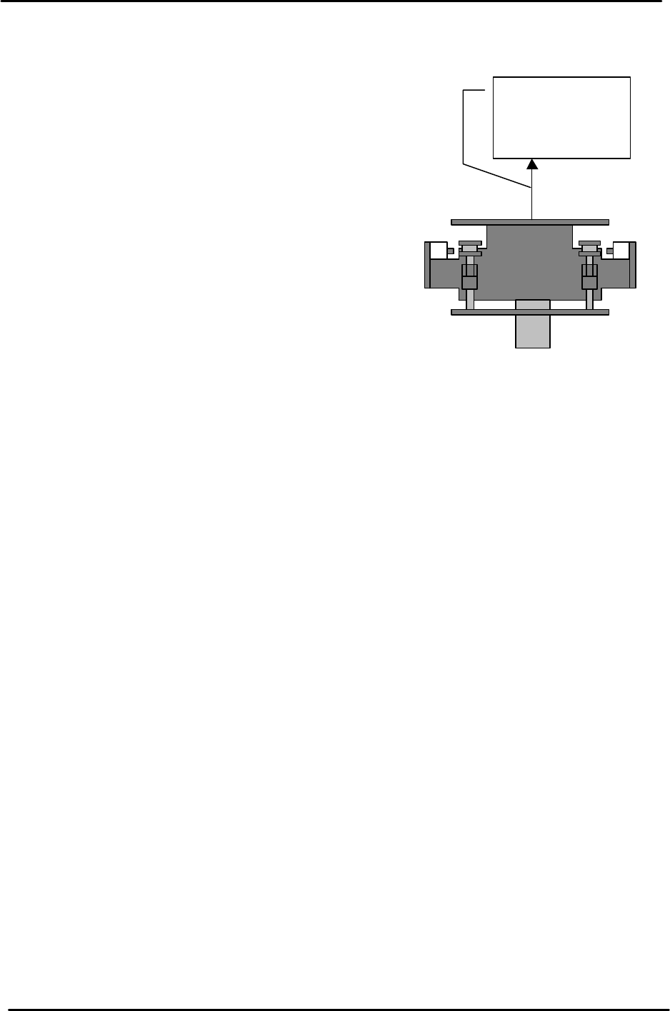
Note: for the U-axis setting pull and hold the U shuttle against the plus mechanical
stopper (MTU Side), and then press the [Direct Servo Input] key.
The shuttle is
pulled towards
the MTU side.