xp141-241-341-5.0E.pdf - 第107页
FK-9F98- 29 XP Series Training Test for Service Engineers Edition 5.0 XP241 – Chapter 3 Static Accuracy Measurement Page 2 of 6 Fuji Machine Mfg. Co., Ltd. Okazaki SMT Equipment Quality Assurance Dept . 3 – 2 CS Section …
FK-9F98-29 XP Series Training Test for Service Engineers
Edition 5.0 XP241 – Chapter 3 Static Accuracy Measurement Page 1 of 6
Fuji Machine Mfg. Co., Ltd. Okazaki
SMT Equipment Quality Assurance Dept.
3 – 1 CS Section
Chapter 3 Static Accuracy Measurement
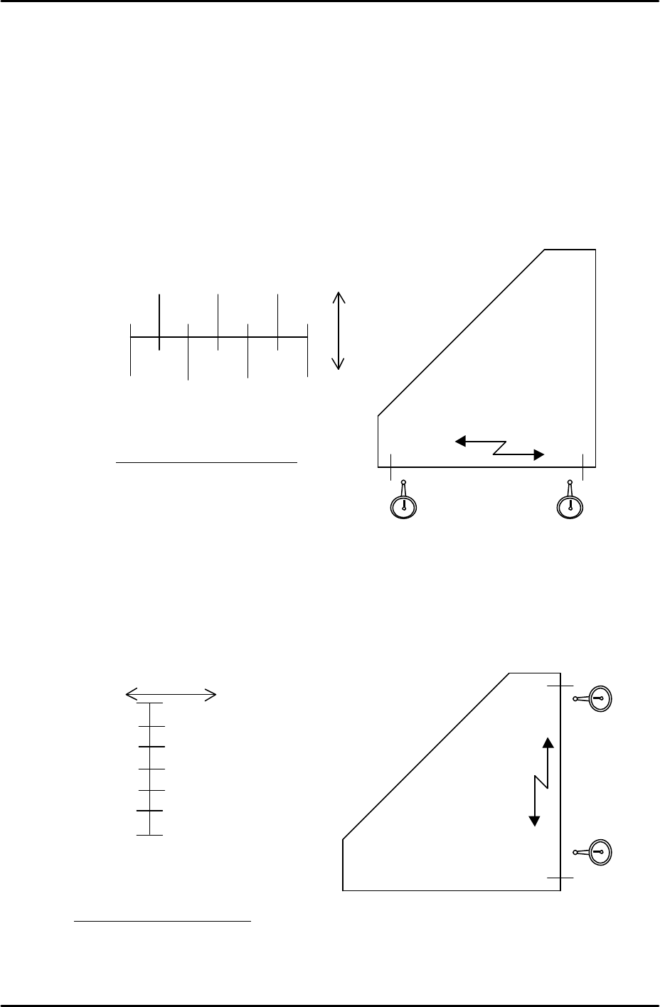
3.1 Checking the straightness of the X/Y axes
• Jig: Perpendicular measurement jig Z9531DEPJ0050.
• Equipment: Lever type dial gauge (0.01mm).
1. Attach the dial gauge to the placement head (an extension bar is necessary).
2. Place the perpendicular measurement jig (Z9531DEPJ0050) on to the main conveyor.
Adjust the jig position so that when running the dial gage along the jig in the X direction,
the 0mm and 300mm point values are both 0 (i.e. the jig is parallel to the X axis).
Note: If the XY-axis squareness needs to be measured, it is better to perform
measurement (3.2) first, before measuring the Y-axis straightness.
3. Measure the Y-axis straightness in the same way as the X-axis.
Note: measure in the part placement area of the main conveyor.
250 150 50
300 200 100 0
( ) ( ) ( )
0 ( ) ( ) 0
+
-
Tolerance: 0.06/300 (mm)
0 0X-direction
Z9531DEPJ0050
300mm
point
0 point
Movement distance of the X-axis
0
( )
( )
( )
( )
( )
0
300
250
100
150
100
50
0
+ -
Movement distance of the Y-axis
0
0
Y-direction
Z9531DEPJ0050
Tolerance: 0.06/300 (mm)
300mm
point
0 point
FK-9F98-29 XP Series Training Test for Service Engineers
Edition 5.0 XP241 – Chapter 3 Static Accuracy Measurement Page 2 of 6
Fuji Machine Mfg. Co., Ltd. Okazaki
SMT Equipment Quality Assurance Dept.
3 – 2 CS Section
3.2 Measuring the squareness of the XY axis
• Jig: Perpendicular measurement jig (Z9531DEPJ0050).
• Equipment: Lever type dial gauge (0.01mm).
1. Load the perpendicular measurement jig on
the conveyor, and position it so that the X-side
is parallel with the X-axis.
2. With the jig in this position, measure the Y-
direction side. This indicates the Y-axis
orientation which is perpendicular to the X-
axis.
Note: measure in the part placement area of
the main conveyor.
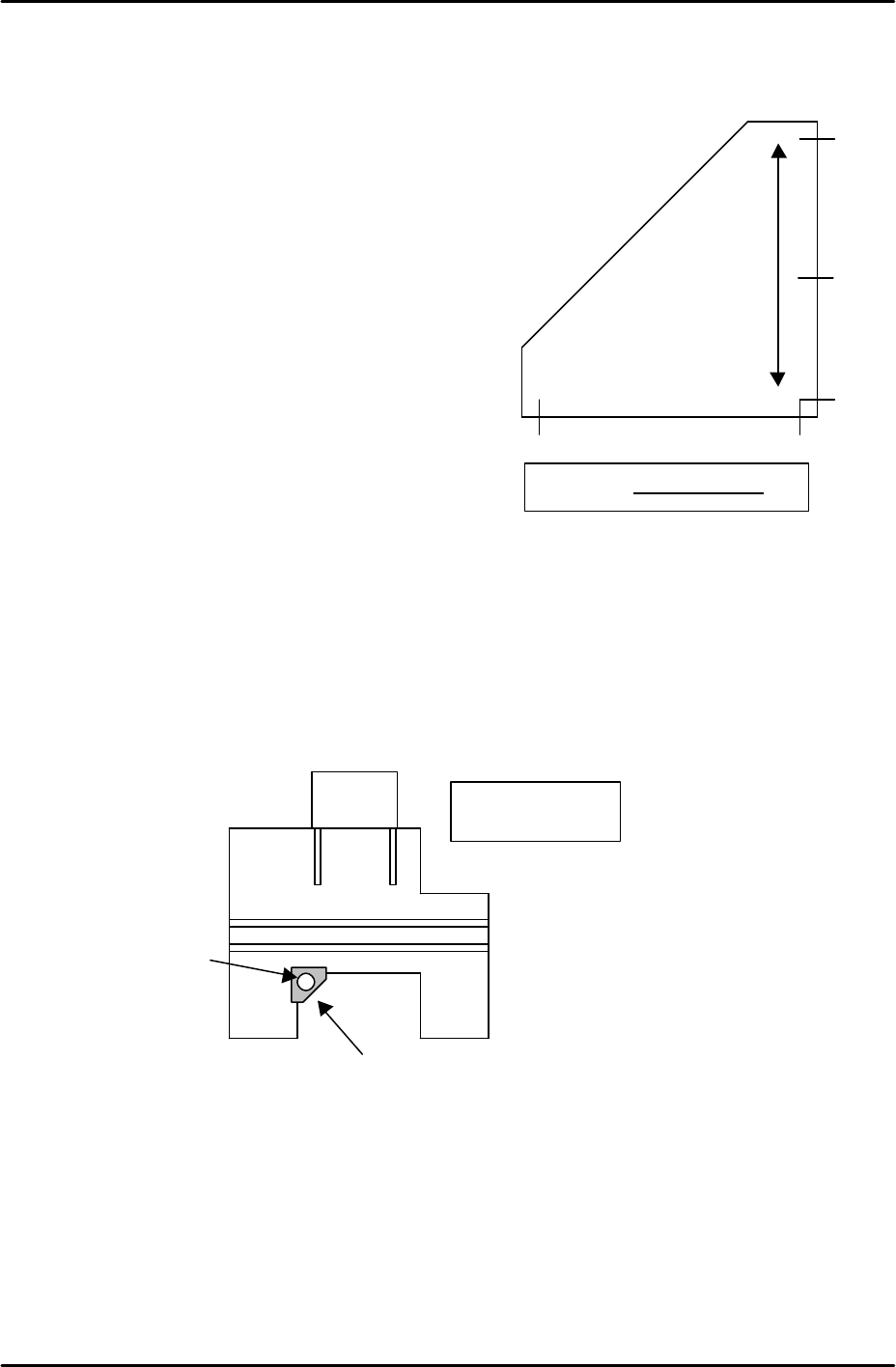
3.3 Z-axis verticality measurement
• Jig: Cylindrical jig (Z9531DEPJ0060).
• Jig: Platform plate jig (Z9531DEPJ1080).
• Equipment: Lever type dial gauge (0.002mm).
1. Set the platform plate jig as shown in the diagram below. Set the cylindrical jig on the
platform plate jig. Ensure that no dirt, parts, or other foreign matter obstruct the balance
of the jigs.
2. Set a mini magnetic dial gauge stand on the placing head at the end of the Z axis spline
shaft. Set the tip of the dial indicator on the most forward part of the cylindrical jig vertical
surface (point C in the diagram below).
3. Measure the straightness of the Z-axis. The range of measurement is from 2mm above
the minus stopper to 32mm above the minus stopper (a stroke of 30mm).
0 0
0
( )
( )
300mm
Z9531DEPJ0050
Tolerance 0.06/300 (mm)
The top view of
the machine
Set the platform plate jig
(Z9531DEPJ1080) on the left side
corner of the machine front base.
Load the cylindrical
jig
(Z9531DEPJ0060)
on the perpendicular
measurement jig.
FK-9F98-29 XP Series Training Test for Service Engineers
Edition 5.0 XP241 – Chapter 3 Static Accuracy Measurement Page 3 of 6
Fuji Machine Mfg. Co., Ltd. Okazaki
SMT Equipment Quality Assurance Dept.
3 – 3 CS Section
4. The difference in straightness between these two points should be within 0.03mm.
5. Repeat for the right hand side of the cylindrical jig.
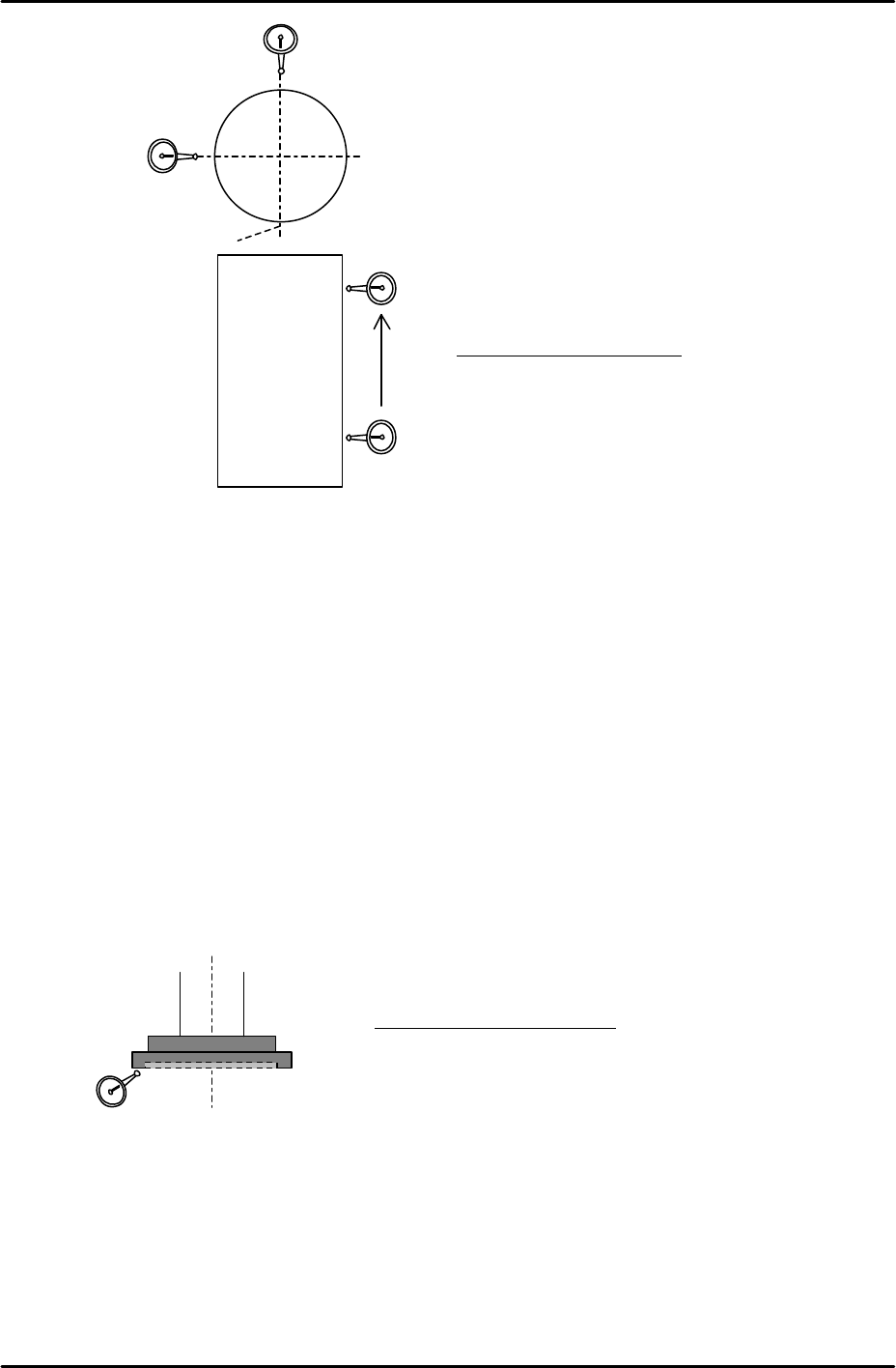
3.4 Checking the Z-axis nozzle disc surface
• Equipment: Lever type dial gauge (0.002mm).
Face oscillation measurement
1. Position the Z axis 2 mm above the Z-axis minus stopper.
2. Put a dial indicator against the underside of the nozzle disc and measure the surface
oscillation by turning the Q-axis through 360 degrees.
Nozzle pick-up surface parallelism measurement
1. Position the nozzle pick-up surface 2 mm above the Z-axis minus stopper.
2. Set a dial gauge on the underside of the nozzle disc, and measure the difference in
flatness from one side of the disc underside to the other. Measure in both the X and the
Y-direction.
Tolerance 0.030 / 30mm
Tolerance: 0.02mm / 360°
X-direction
Y-direction
A
0
Z9531DEPJ0060
30mm
C