xp141-241-341-5.0E.pdf - 第112页
C C h h a a p p t t e e r r 4 4 L L o o a a d d e e r r A A d d j j u u s s t t m m e e n n t t

FK-9F98-29 XP Series Training Test for Service Engineers
Edition 5.0 XP241 – Chapter 3 Static Accuracy Measurement Page 6 of 6
Fuji Machine Mfg. Co., Ltd. Okazaki
SMT Equipment Quality Assurance Dept.
3 – 6 CS Section
3.9 Backlash calibration
• Equipment: Lever type dial gauge (0.002mm).
1. Set the dial gauge to the X and Y-axes. Turn the 200V servo power ON. Measure any
backlash in the X and Y axes movement.
2. For the Q-axis, adjust it so there is no backlash.
Tolerance: within 0.010 mm

C
C
h
h
a
a
p
p
t
t
e
e
r
r
4
4
L
L
o
o
a
a
d
d
e
e
r
r
A
A
d
d
j
j
u
u
s
s
t
t
m
m
e
e
n
n
t
t
FK-9F98-29 XP Series Training Text for Service Engineers
Edition 5.0 XP241 – Chapter 4 Loader Adjustment Page 1 of 12
Fuji Machine Mfg. Co., Ltd. Okazaki.
SMT Equipment Quality Assurance Dept.
4 – 1 CS Section
Chapter 4: Loader Adjustment
4.1 Measuring the Flatness of the Lifter Plate
• Measuring equipment: standard lever type dial gauge (0.01mm).
1. Adjust the conveyor to its maximum width
(356mm), and then remove the back-up plate.
Note: Do not use the conveyor auto width
changer, as this is not adjusted yet.
2. Loosen the lock nuts on the clamper height
adjustment bolts.
3. Raise the main lifter.
Note: There should be some clearance between the
lifter plate and clamper height adjustment bolts. If there is no clearance between them screw
the clamper height adjustment bolts in to achieve clearance.
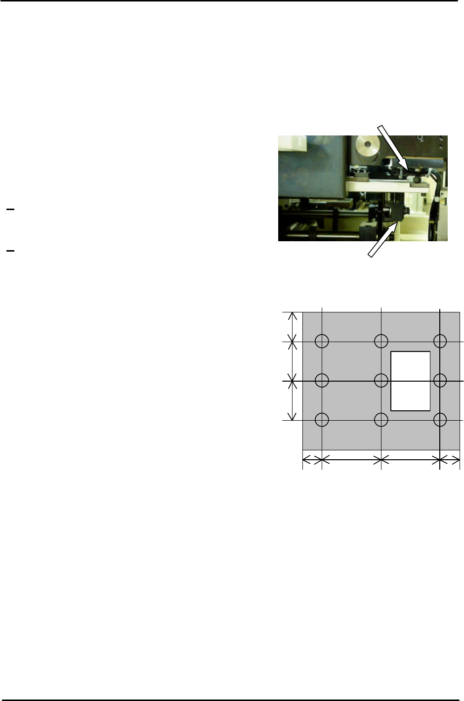
4. Attach the dial gauge to the placing head (an
extension bar is necessary).
Measure the Four Corners of the table
(Points: A, C, G, and I); ensure each value is
0. If the table is not flat, re-adjust it using the
four height adjustment bolts.
5. After ensuring the four-corners of the table are
flat, measure the surface of the table at the
nine positions shown in the diagram. Any
deviation should be within 0.10mm. If the
values are out of tolerance please contact
FUJI.
4.2 Measuring the Flatness and Parallelism of the Fixed Rail
Parallelism of the Fixed Rail
• Measuring equipment: standard lever type dial gauge (0.01mm).
1. Attach the dial guage to the placing head (an extension bar is necesarry).
2. Set the dial gauge to the reference side of the conveyor.
3. Set the dial gage to “0”. Measure the parallelism of the fixed rail.
4. Record your measurements on the adjustments check sheet:
Height adjustment bolt
Clamper height adjustment bolt
I H G
F E D
C B A
180 180 5050
80
110
110