xp141-241-341-5.0E.pdf - 第12页
FK-9F98- 29 XP Series Training Text for Service Engineers Edition 5.0 XP141 – Chapter 1 Initial Adjustment Page 2 of 6 Fuji Machine Mfg. Co., Ltd.Okazaki SMT Equipment Quality Assurance Dept. 1 – 2 CS Section Air hose co…
FK-9F98-29 XP Series Training Text for Service Engineers
Edition 5.0 XP141 – Chapter 1 Initial Adjustment Page 1 of 6
Fuji Machine Mfg. Co., Ltd.Okazaki
SMT Equipment Quality Assurance Dept.
1 – 1 CS Section
Chapter – 1 Initial Adjustment
1.1 Leveling
1. Place two track levels at position A, shown in the following diagram:
2. Carry out initial leveling at points 1,2,3,4, then lock all 8 leveling sheets.
3. Leveling tolerance is 0.10mm/1000mm.
1.2 Power and Air connection
Power supply connection
1. Open the power supply BOX at the lower right hand
side of the machine and pull the power line from the
bottom of the BOX.
2. Connect the ground terminal and the ground wire first.
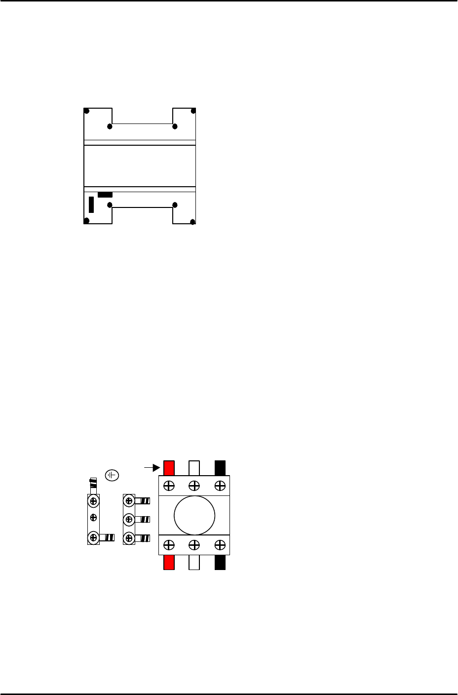
3. Connect the three wires of the power supply cable to the three breaker box (KG41B)
terminals.
L1: red L2: white L3: black
A
1
23
4
L1 L2 L3
Red
FK-9F98-29 XP Series Training Text for Service Engineers
Edition 5.0 XP141 – Chapter 1 Initial Adjustment Page 2 of 6
Fuji Machine Mfg. Co., Ltd.Okazaki
SMT Equipment Quality Assurance Dept.
1 – 2 CS Section
Air hose connection
1. Connect the hose to the air inlet at the machine.
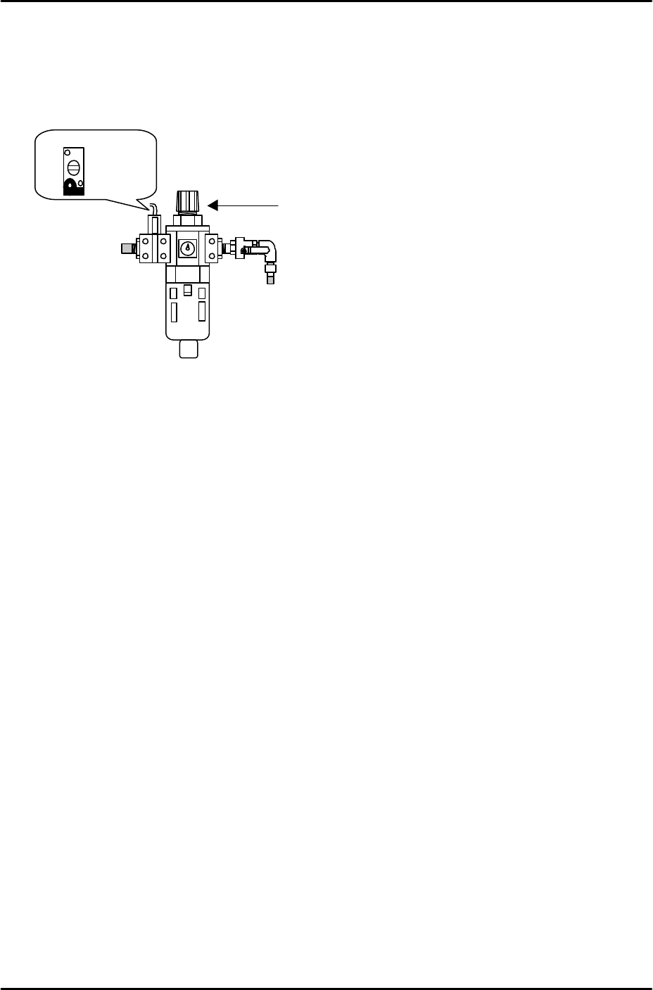
2. Pull up on the regulator knob to release the lock.
3. Turn the regulator knob until the pressure level indicated at the regulator shows 0.5Mpa
(5kgf/cm2).
4. Push down the regulator knob to lock it.
5. Adjust the screw on the vacuum sensor so that the 200-volt power supply to the servos
cuts out when the air pressure drops to 0.4Mpa and below.
6. Select [Maintenance A] – [I/O Check] – [Y016 VacuumPump] – [ON] and confirm that the
vacuum pump dial shows negative pressure.
7. If the dial indicates that the vacuum pump is rotating in the wrong direction the power
cable connection is probably reversed.
8. In this case turn the machine power OFF, trip the breaker and disconnect the power cable
from the mains socket.
9. Check that the power supply connection is correct, and then confirm the power cable is
not reverse phased.
Vacuum Sensor
Regulator Knob
FK-9F98-29 XP Series Training Text for Service Engineers
Edition 5.0 XP141 – Chapter 1 Initial Adjustment Page 3 of 6
Fuji Machine Mfg. Co., Ltd.Okazaki
SMT Equipment Quality Assurance Dept.
1 – 3 CS Section
1.3 Lubrication
1. Apply lubricants to the following areas:
Lubrication points Lubrication Type
Y-axis ball screw Daphne Eponex No.2
Z-axis ball screw Daphne Eponex No.2
Spline Shaft Daphne Eponex No.2
Theta and R axes gears Daphne Eponex No.2
Conveyor ball screw Daphne Eponex No.2
Conveyor LM rail Daphne Eponex No.2
Sliding parts of lifter plate link arm Daphne Eponex No.2
Sliding parts of cutter link arm Daphne Eponex No.2
Cutter LM rail Daphne Eponex No.2
F and G axes cams Daphne Eponex No.2
Nozzle Pistons AFC Grease
Spool Axes AFC Grease
Conveyor Chain Biral T and D
Note: Apply anticorrosion spray to the machine base, brackets, and other metal surfaces, to prevent
rust.
Note: Do not over apply lubricant to the ball screws, helical gears, LM guide rails, or other parts of the
machine that rotate or move at high velocity. Over lubrication may result in the lubricant being flung
around the machine and interfering with the sensors, vision processing, and other aspects of the
machine operation.
Note: If any of the spool axes (vacuum and air blow pins) need removing the pins should be pulled
out from the top of the revolver. Previously they could be removed from the bottom of the revolver,
however an O-ring has been added to prevent the pins from slipping down erroneously, making it
necessary to remove the pins from the top. In order to facilitate this the vacuum and air blow pins are
now designed in two pieces so that the stopper at the bottom of the pins can be unscrewed. Before
replacing any pins in the revolver apply a thin layer of AFC grease. When attaching the stopper to the
pin, Loctite adhesive should be applied to the screw thread.
1.4 Belt tension measurement
1. Equipment: belt tension meter (U-505).
2. Press the emergency stop button to cut the 200-volt power supply to the servos and then
bring the Y and Z axes to the minus mechanical stoppers.
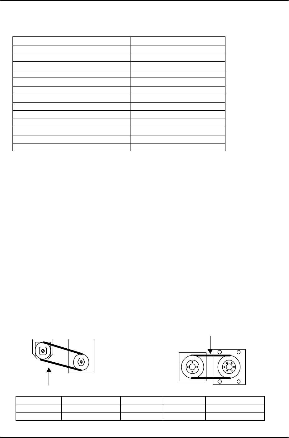
3. Refer to the following illustrations and check that the tension of each belt is within the
appropriate range:
Belt unit weight Belt width Belt span Frequency range
Y axis
0.4 gf/mm 15mm 130mm 165 –183 Hz
Z axis
0.2 gf/mm 8mm 110mm 204 – 226Hz
Y measuring
point
Z measuring
point