xp141-241-341-5.0E.pdf - 第124页
FK-9F98- 29 XP Series Training Text for Service Engineers Edition 5.0 XP241 – Chapter 4 Loader Adjustment Page 12 of 12 Fuji Machine Mfg. Co., Ltd. Okazaki. SMT Equipment Quality Assurance Dept. 4 – 12 CS Section NOTES:
FK-9F98-29 XP Series Training Text for Service Engineers
Edition 5.0 XP241 – Chapter 4 Loader Adjustment Page 11 of 12
Fuji Machine Mfg. Co., Ltd. Okazaki.
SMT Equipment Quality Assurance Dept.
4 – 11 CS Section
4. 10 Conveyor Width and Movement
• Measuring tool: Calipers (0.05mm)
1. Ensure that the width change can be carried out smoothly, when the conveyor is moved
to its Min. (50mm or less) ~ Max. (356mm or greater) width.
Note: Do not use the conveyor auto width changer, as this is not adjusted yet.
2. Set the entrance of the In-conveyor to 130mm. Check a few points along the conveyor
width from entrance to exit. The difference between the maximum width and minimum
width should be within 0.5mm. If it is out of the tolerance, please contact FUJI.
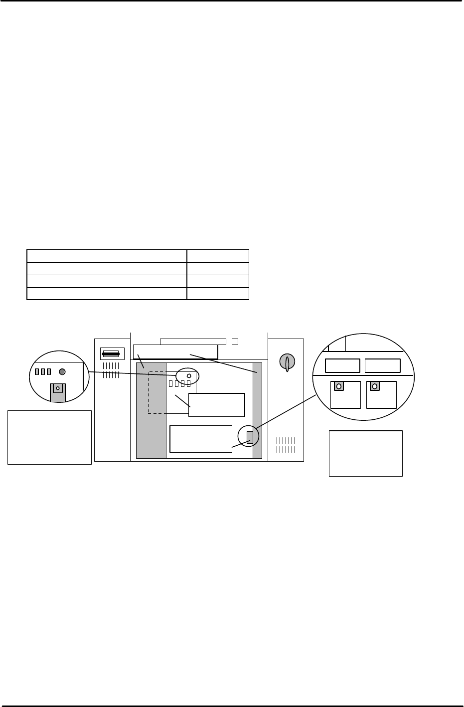
3. The speed of board loading and the speed of the conveyor width changer are set at FUJI
prior to machine shipment. Changing these speeds is not recommended. However for
your reference the location and function of the conveyor speed controllers are given
below:
Loading Function Controller
Board Loading (Normal speed) T1VR1
Board Loading (Deceleration) T1SP1
Conveyor width change T1SP2
T1SP1 T1SP2
Side1; Back of
the right door of
the bottom Box.
T1VR1
Side1: Rear of the
Electric Box, top
left connector on
the main relay
board.
Main relay
board
Speed control
board cover
Electric Box Door

FK-9F98-29 XP Series Training Text for Service Engineers
Edition 5.0 XP241 – Chapter 4 Loader Adjustment Page 12 of 12
Fuji Machine Mfg. Co., Ltd. Okazaki.
SMT Equipment Quality Assurance Dept.
4 – 12 CS Section
NOTES:

C
C
h
h
a
a
p
p
t
t
e
e
r
r
5
5
P
P
e
e
r
r
i
i
p
p
h
h
e
e
r
r
a
a
l
l
A
A
d
d
j
j
u
u
s
s
t
t
m
m
e
e
n
n
t
t
s
s