xp141-241-341-5.0E.pdf - 第127页
FK-9F98- 29 XP Series training Text for Service Engineers Edition 5.0 XP241 – Chapter 5 Peripheral Adjustments Page 2 of 19 Fuji Machine Mfg. Co., Ltd. Okazaki. SMT Equipment Quality Assurance Dept . 5 – 2 CS Section Tra…
FK-9F98-29 XP Series training Text for Service Engineers
Edition 5.0 XP241 – Chapter 5 Peripheral Adjustments Page 1 of 19
Fuji Machine Mfg. Co., Ltd. Okazaki.
SMT Equipment Quality Assurance Dept.
5 – 1 CS Section
Chapter 5 Peripheral Adjustments
In order to carry out adjustments on the MTU it is sometimes necessary to use the T and U axis
jog commands in the [Maintenance A] – [Jog] screen. In machine software version V1.30 and later
versions, the T and U axes are disabled by default as a safety precaution. To enable them for the
duration of the adjustment select [Maintenance C] – [Proper Data Editor] – [OPERATION_2] –
[JogInterlockOFF] and change the value from 0 to 1. After the adjustment is complete, remember
to return this to its original value. The following adjustment procedure is for the old type of MTU,
for the new type of MTU (type 2) refer to chapter 9 of this manual.
5.1 Adjusting the MTU (old type)
Note: Be extremely careful when operating the MTU, especially
when trays are inside.
Tray stopper adjustment
1. Remove the plastic covers from the MTU door.
2. Put trays in the magazine top and bottom shelves.
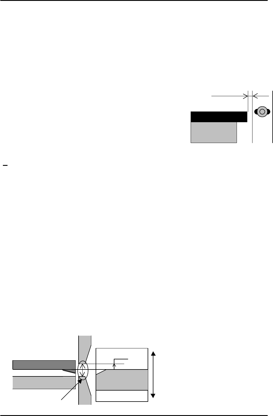
3. With the door closed set the gap between the long white plastic stopper on the door and
the trays to 0.5 – 1.0mm.
Note: ensure that the gap between the long white stopper and the trays is 0.5 to 1.0 mm
at all positions up and down the T axis.
Tray conveyance position measurement
1. Position the M.T.U magazine at the position where the bottom rung [01, 02] is level with
the U axis conveyor surface. Input this position in [Maintenance C] – [Proper Data Editor]
– [Tray] - T_Tray Org.
2. Ensure that the transfer from T axis to U axis is smooth and there is no jolting when trays
are extended and retracted at this height.
Adjusting the Position of the Guide Bar
1. Set a tray shelf at tray position [01, 02] and bring it to the T_Tray Org position.
2. Set the bottom edge of the upper guide bar 8 mm above the surface of the tray shelf.
3. Set the top edge of the lower guide bar 10 mm below the bottom edge of the upper guide
bar.
Tray
0.5 ~1.0mm
Adjust the height to align the Tray
reference rail and No.01 tray height.
No.01 tray
Tray reference rail
Upper guide bar
Lower guide bar
10mm
8mm
FK-9F98-29 XP Series training Text for Service Engineers
Edition 5.0 XP241 – Chapter 5 Peripheral Adjustments Page 2 of 19
Fuji Machine Mfg. Co., Ltd. Okazaki.
SMT Equipment Quality Assurance Dept.
5 – 2 CS Section
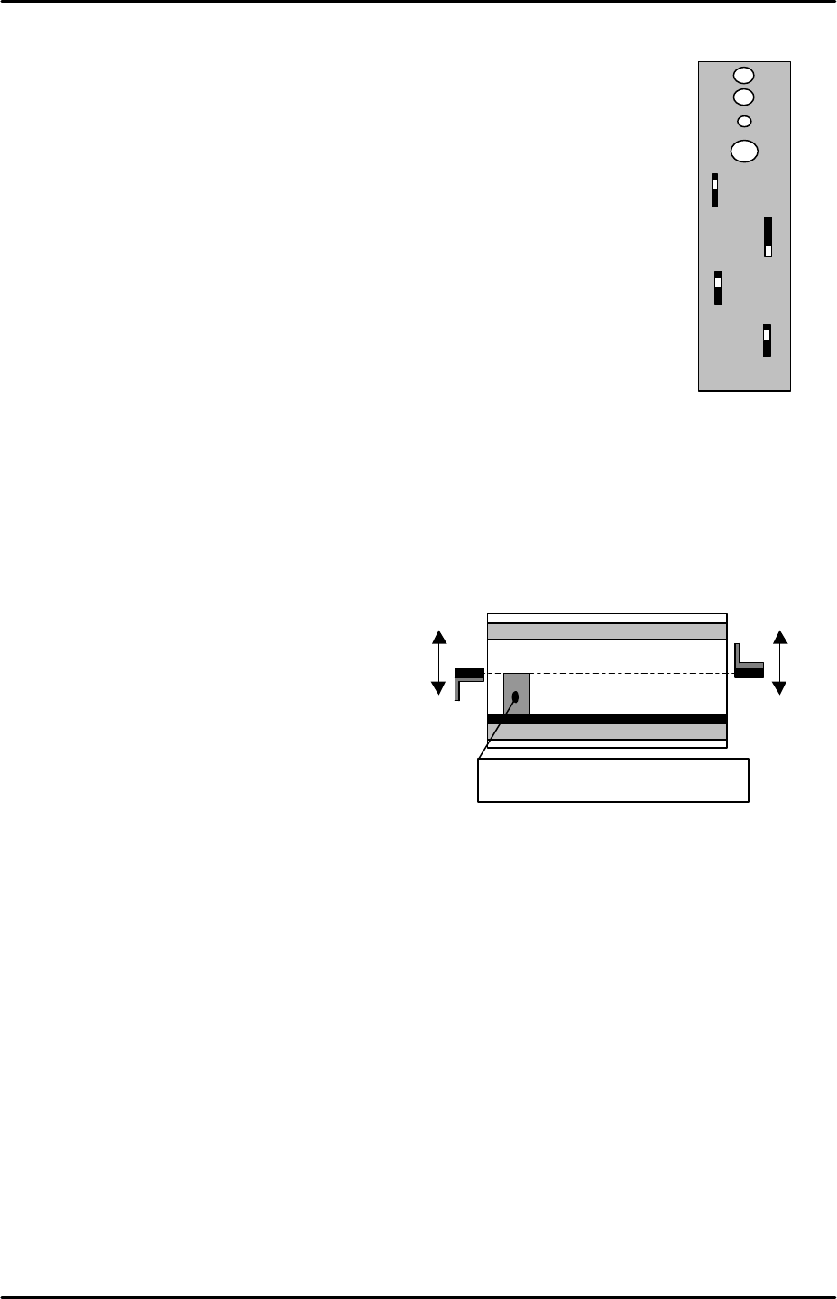
Tray height check sensor adjustment
Jig: 33mm height block jig (Z5704DEPJ0010).
1. Ensure the tray height check sensor amplifiers are set according to the
adjacent diagram.
2. Set a tray at tray position 01 and bring it to the T_Tray Org position.
3. Mount the 33 mm block jig (Z5704DEPJ0010) on the tray shelf jig, and
adjust the sensors (front/rear) so that they just detect the top of the
block.
4. Adjust the sensors for tray position 02 in the same manner.
5. Ensure the I/Os X03A TrayheightChk1 and X03B TrayHeightChk 2 turn ON when the
sensors are interrupted.
6. After adjusting the position of the sensors, go on to the automatic sensor beam
adjustment.
Automatic sensor beam adjustment
1. Release the lock on the sensor amplifier.
2. When the sensor is not being interrupted press [SET]. The SET lamp comes ON.
3. With the sensor interrupted press [SET].
4. The adjustment of the sensor is complete when the SET lamp turns OFF. Reset the lock
on the amplifier.
5. Ensure that the tray is in tray position 1 then select [Maintenance A] – [Jog] – [T-axis] and
raise the tray unit. Input the position that the tray height sensors are interrupted by the
top of the tray to [Maintenance C] – [Proper Data editor] – [Tray] – [T_Tray Empty Org] –
[Direct Servo Input].
SET
LOCK
OFF.D
ON.D
OFF
D.ON
L.ON
FINE
TURBO
PS - T1
Block jig (Z5704DEPJ0010)
FK-9F98-29 XP Series training Text for Service Engineers
Edition 5.0 XP241 – Chapter 5 Peripheral Adjustments Page 3 of 19
Fuji Machine Mfg. Co., Ltd. Okazaki.
SMT Equipment Quality Assurance Dept.
5 – 3 CS Section
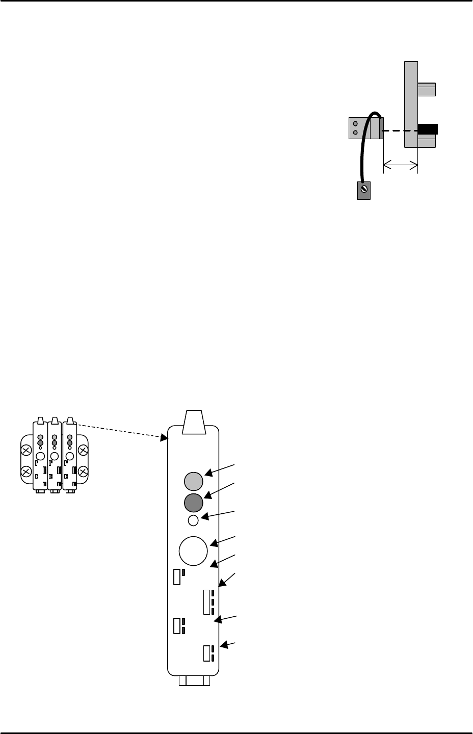
Tray detection sensor adjustment
1. Set a tray at tray position 1 and bring the T axis to the T_Tray
Org position.
2. Set the sensor volume to its maximum (clockwise).
3. Position the sensor 20 mm from the tray’s leading edge and
adjust the position of the sensor so that its beam is centered
on the tray side.
4. Ensure the I/O X038 M.PosTrayDetect turns ON when the
sensor is interrupted.
MTU interlock sensor adjustment
Equipment: MTU Interlock Sensor Jig (Z9631DEPJ3101).
1. Remove three trays from the middle of the MTU magazine.
2. Close the MTU door and select [Manual Operation] – [Tray Operation] – [Slot] – [Here
choose the slot number of the lowest of the removed trays] and then press [Move
elevator] to move the magazine to the loading position for that tray.
3. The amplifier for the interlock sensor is located to the right of the two tray height check
sensor amplifiers. To set the amplifier carry out the following procedure:
4. Verify that the amplifier is set as follows:
20mm
Set the volume
to MAX.
Tray detection
sensor
Output timer changeover switch
SET
LOCK
OFF.D
ON.D
OFF
D.ON
L.ON
FINE
TURBO
Operation indicator lamp (Red LED)
Stable operation indicator (Green LED)
Tuning indicator (Yellow LED)
SET button
Key-Protect switch
Output changeover switch
FINE/TURBO toggle switch