xp141-241-341-5.0E.pdf - 第135页
FK-9F98- 29 XP Series training Text for Service Engineers Edition 5.0 XP241 – Chapter 5 Peripheral Adjustments Page 10 of 19 Fuji Machine Mfg. Co., Ltd. Okazaki. SMT Equipment Quality Assurance Dept . 5 – 10 CS Section 5…

FK-9F98-29 XP Series training Text for Service Engineers
Edition 5.0 XP241 – Chapter 5 Peripheral Adjustments Page 9 of 19
Fuji Machine Mfg. Co., Ltd. Okazaki.
SMT Equipment Quality Assurance Dept.
5 – 9 CS Section
3. Set the dial to 0. Jog in the Y-direction to detach the dial gage tip from the jig. Record the
present X-axis servo counter. Unclamp the MFU.
4. Clamp another MFU, then mount the device jig to device No.2 and turn the servo ON. Jog
the X axis and check the difference in the X-direction.
5. Repeat the procedure for any other MFUs
Device I/O port check
1. Load the device I/O check feeder on the device table, and use direct I/O (Y040
PartsSendD1) and (Y07F PartsSendD40) to check that all the device position I/0s are
operational.
Note: Use some cloth to wipe any dirt from the MFU connectors.
5.3 MFU sensor adjustments
MFU tape leaf check sensors
Currently there are two different types of MFU tape leaf check sensors, both types are
manufactured by Yamatake. The serial number for the old LED type is: HPJ-T23. The
serial number for the newer double detection fiber type sensor is: HPF-T003 (Fiber) and
FE-PA-S1 (Attachment). The double detection fiber type sensors are supported from
machine software version V1.40 for XP241E.
Yamatake LED type (HPJ-T23)
1. Attach the MFU to the machine. Check that I/O X02D Side 1 MfuConChek turns ON.
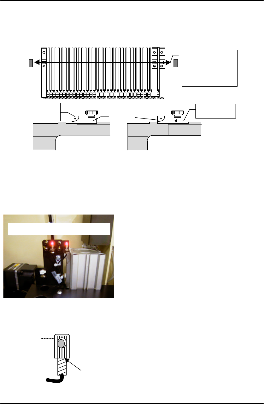
2. Mount the feeder leaf check sensor adjustment jig (Z9631ADEPJ980) at device positions
D38 & 40 on Side 1.
3. Insert the 1.8 mm diameter rod jig in both slits, and and temporarily adjust the sensor so
that the beam beam passes through the center of the jig. Also check that the sensor is not
tilted.
4. Move the jig to D1 & D3, temporarily adjust the sensor receiver side.
X-direction
Tolerance: within 0.050mm
FK-9F98-29 XP Series training Text for Service Engineers
Edition 5.0 XP241 – Chapter 5 Peripheral Adjustments Page 10 of 19
Fuji Machine Mfg. Co., Ltd. Okazaki.
SMT Equipment Quality Assurance Dept.
5 – 10 CS Section
5. Mount the jig set at D3 to D40. Move one side of the jig slit towards yourself, then the
other; eachtime ensuring that the I/O signal, X017 Side1 XYAxis Inter, turns OFF.
Yamatake double detection fiber type sensor
Initial setting
1. Fix the attachment to the fiber sensor using Loctite 222 adhesive.
Adjust the sensor so
that the beam
passes through the
center of the jig.
Sensor beam
position
Slit
Check after
moving the slit
Sensor ON
Sensor OFF
Double detection type tape leaf sensors
Attachment
Fiber sensor
Apply Loctite 222 here
FK-9F98-29 XP Series training Text for Service Engineers
Edition 5.0 XP241 – Chapter 5 Peripheral Adjustments Page 11 of 19
Fuji Machine Mfg. Co., Ltd. Okazaki.
SMT Equipment Quality Assurance Dept.
5 – 11 CS Section
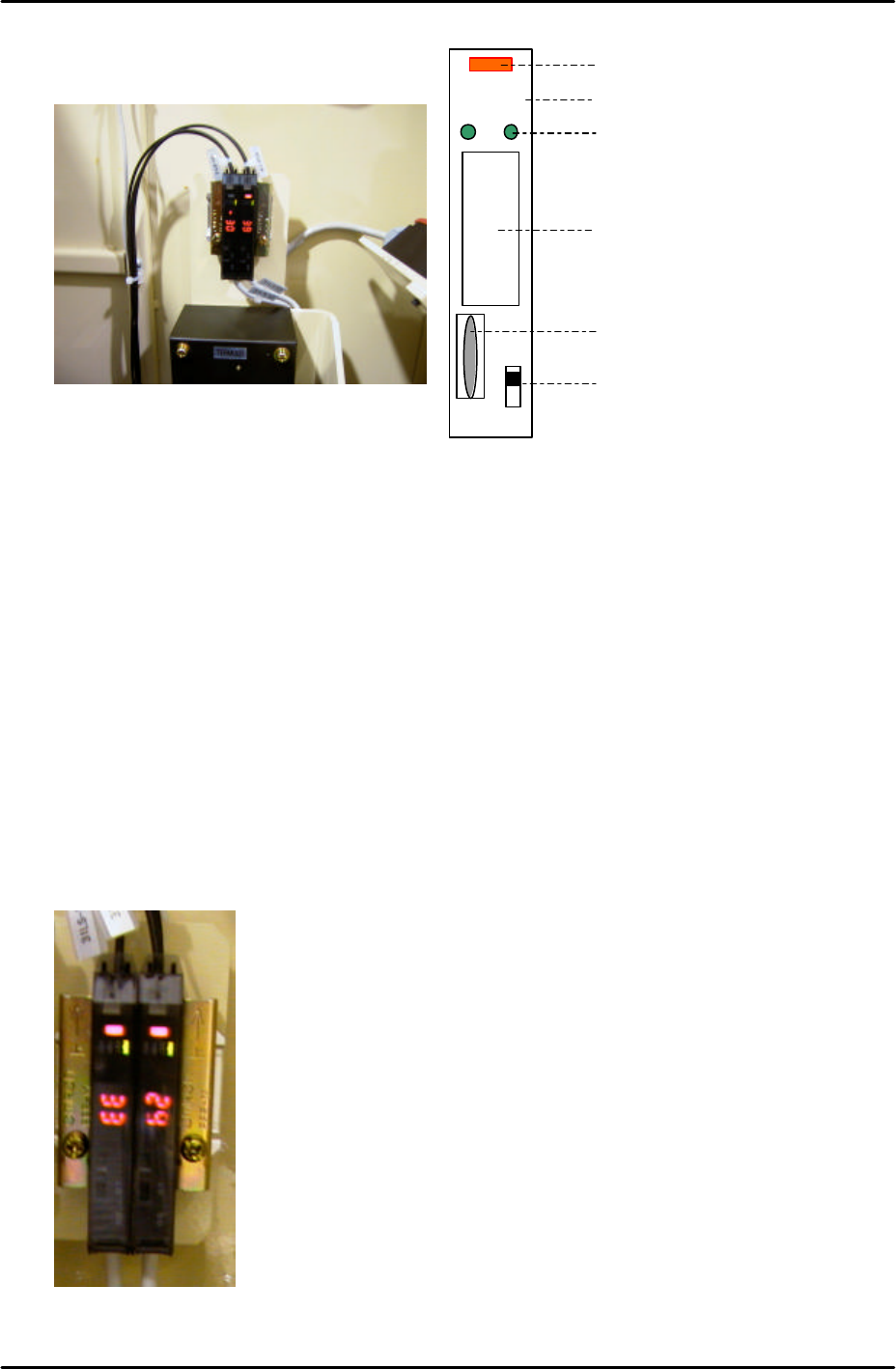
Amplifier frequency setting
1. Set the L-ON/D-ON changeover switch to L_ON.
2. Press the dial switch once (the RUN light in the Mode Display flashes and “AA” is
displayed on the digital display).
3. Turn the dial switch until SET flashes on the “Mode Display”.
4. Press and hold the dial switch for 3 seconds (SET stops flashing and the Mode Lights
come ON).
5. Turn the dial switch until “– –“ is displayed on the digital display.
6. Press and hold the dial switch for 8 seconds.
7. Turn the dial to select F1 or F2 depending on which of the two amplifiers are being
adjusted (refer to the photo of the amplifiers below).
LO DO
RUN
SET
TMR
ADJ
Digital Display
Operation Light
L-ON/D-ON Changeover Switch
Dial Switch
Mode Display
Mode Lights
F1F2
Side 1