xp141-241-341-5.0E.pdf - 第137页
FK-9F98- 29 XP Series training Text for Service Engineers Edition 5.0 XP241 – Chapter 5 Peripheral Adjustments Page 12 of 19 Fuji Machine Mfg. Co., Ltd. Okazaki. SMT Equipment Quality Assurance Dept . 5 – 12 CS Section 8…
FK-9F98-29 XP Series training Text for Service Engineers
Edition 5.0 XP241 – Chapter 5 Peripheral Adjustments Page 11 of 19
Fuji Machine Mfg. Co., Ltd. Okazaki.
SMT Equipment Quality Assurance Dept.
5 – 11 CS Section
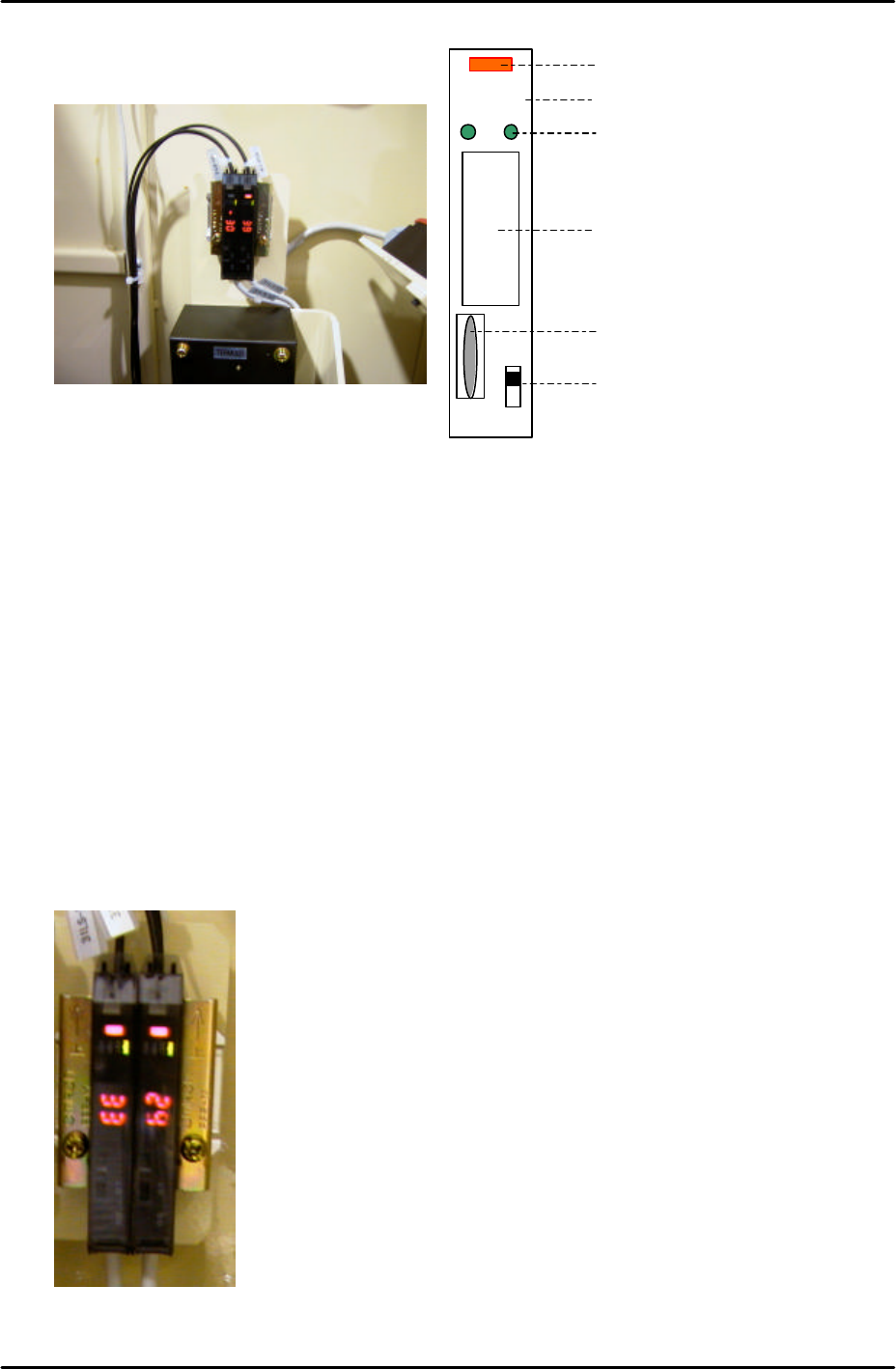
Amplifier frequency setting
1. Set the L-ON/D-ON changeover switch to L_ON.
2. Press the dial switch once (the RUN light in the Mode Display flashes and “AA” is
displayed on the digital display).
3. Turn the dial switch until SET flashes on the “Mode Display”.
4. Press and hold the dial switch for 3 seconds (SET stops flashing and the Mode Lights
come ON).
5. Turn the dial switch until “– –“ is displayed on the digital display.
6. Press and hold the dial switch for 8 seconds.
7. Turn the dial to select F1 or F2 depending on which of the two amplifiers are being
adjusted (refer to the photo of the amplifiers below).
LO DO
RUN
SET
TMR
ADJ
Digital Display
Operation Light
L-ON/D-ON Changeover Switch
Dial Switch
Mode Display
Mode Lights
F1F2
Side 1

FK-9F98-29 XP Series training Text for Service Engineers
Edition 5.0 XP241 – Chapter 5 Peripheral Adjustments Page 12 of 19
Fuji Machine Mfg. Co., Ltd. Okazaki.
SMT Equipment Quality Assurance Dept.
5 – 12 CS Section
8. Press the dial switch once so that SET in the Mode Display flashes.
9. Turn the dial until RUN in the mode display flashes.
10. Press the dial switch once (RUN stops flashing and a number 1~100 displays in the
digital display).
11. Repeat the procedure for the other amp.
HP mode and sensor position setting
1. Press the dial switch once (the RUN light in the Mode Display flashes and “AA” is
displayed on the digital display).
2. Turn the dial switch until SET flashes on the “Mode Display”.
3. Press and hold the dial switch for 3 seconds (SET stops flashing and the Mode Lights
come ON).
4. Turn the dial switch until “HP” is displayed on the digital display.
5. Press the dial switch once (SET in the mode display flashes).
6. Press the dial switch once so that “2P” flashes on the digital display.
7. Turn the dial until a number 1~100 displays on the digital display.
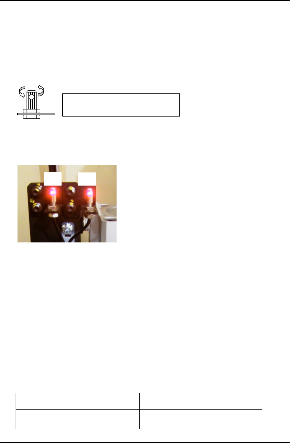
8. Clamp the MFU and set sensor adjustment jigs (Z9731ADEPJ8070) in slots D38 and
D40. When adjusting the F1 sensor use the outer sensor light beam adjustment
attachment (Z5531DEPJ9010). When adjusting the F2 sensor use the inner sensor light
beam adjustment attachment (Z9317ABHPJ9300).
F1
D40D38
F2
Attachment for F1 sensor
(Z5531DEPJ9010)
Attachment for F2 sensor
(Z5531DEPJ9300)
FK-9F98-29 XP Series training Text for Service Engineers
Edition 5.0 XP241 – Chapter 5 Peripheral Adjustments Page 13 of 19
Fuji Machine Mfg. Co., Ltd. Okazaki.
SMT Equipment Quality Assurance Dept.
5 – 13 CS Section
9. Make sure the attachments on the jig are pulled to the rear of the jig (away from the
machine interior).
10. Insert a 1.8mm diameter wire jig through both holes in the sliding attachments and adjust
the position of the sensor so that the point where the sensor beam is emitted is aligned
with the center of the wire jig.
11. Confirm that the fiber sensor attachment is securely fixed to the fiber sensor.
12. Now fine adjust the position of the sensors to find the position where the number on the
digital display is maximised. This maximum value should be greater than 3. If the value
is 3 or less check the fiber wiring and clean the sensor lens.
13. After the sensors have been set at the optimum position turn the dial switch on the
sensor amplifier until “2P” flashes in the digital display.
14. Press the dial once so that the “2” in “2P” flashes.
15. Block the sensor by hand and press the dial switch once. A number 1~100 will display on
the digital display, this must be greater than 10.
16. Press the dial switch once so that SET flashes in the mode display.
17. Turn the dial switch so that RUN flashes in the mode display.
18. Press the dial switch once to complete the adjustment.
19. Finally select [Maintenance A] – [I/O Check] and check the sensor operation by I/O.
There is only one I/O channel:
Sensor I/O Output when not
interrupted
Output when
interrupted
F1/F2 X026 Side1 TpsetDetect O (with buzzer) X
Make sure that it is not possible to turn
the fiber sensor attachment by hand
F1F2
Side 1