xp141-241-341-5.0E.pdf - 第140页
FK-9F98- 29 XP Series training Text for Service Engineers Edition 5.0 XP241 – Chapter 5 Peripheral Adjustments Page 15 of 19 Fuji Machine Mfg. Co., Ltd. Okazaki. SMT Equipment Quality Assurance Dept . 5 – 15 CS Section 5…
FK-9F98-29 XP Series training Text for Service Engineers
Edition 5.0 XP241 – Chapter 5 Peripheral Adjustments Page 14 of 19
Fuji Machine Mfg. Co., Ltd. Okazaki.
SMT Equipment Quality Assurance Dept.
5 – 14 CS Section
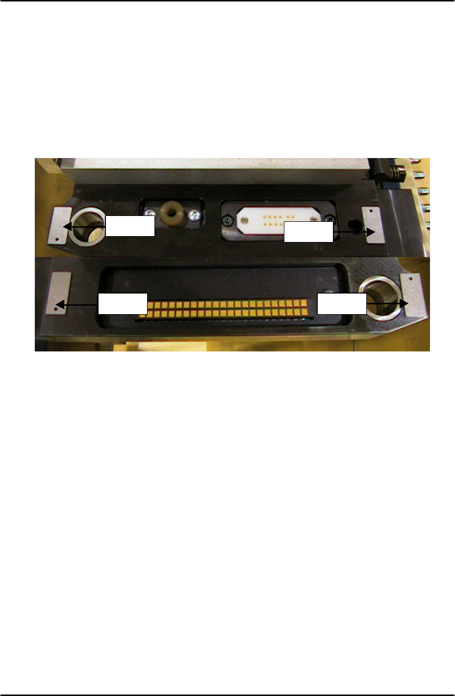
MFU cylinder sensor adjustment
1. Note that there are two sensors on each clamping cylinder, making a total of four sensors
on side 1, and four sensors on side 2.
2. The clamp check sensors (X02E side1MfuUpChk) should be adjusted so that they are ON
0.3mm from the clamp upper limit, and OFF 0.8mm from the clamp upper limit. In order
to adjust them, please follow the procedure below:
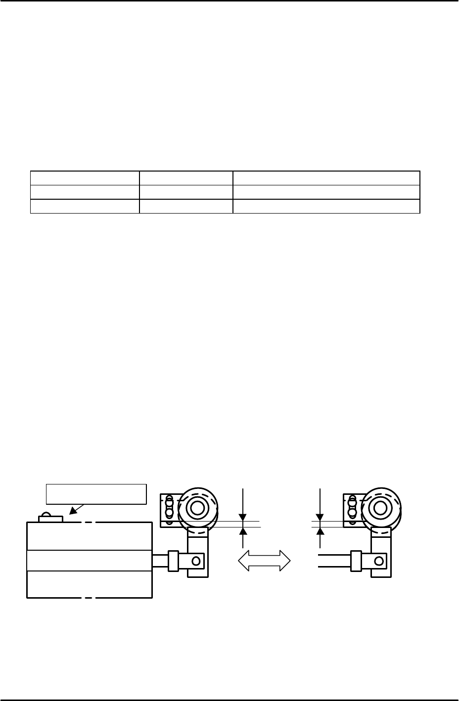
3. Place 0.3mm spacers in the four corners of the MFU clamping surface as illustrated
below:
4. Clamp the MFU.
5. Slide the clamp check sensors DOWN until they go OFF then slide them back UP until
they just come ON then tighten the screw (X02E side1MfuUpChk).
6. Unclamp the MFU and replace the 0.3mm spacers with 0.8mm spacers.
7. Clamp the MFU and confirm that the clamp check sensors (X02E side1MfuUpChk) are
OFF.
8. Unclamp the MFU and slide the unclamp check sensors UP until they go OFF and then
slide them back DOWN until they come ON. From the position they first come ON slide
them a further 1mm DOWN and tighten the screw. (X02F side1MfuDownChk).
9. Repeat the procedure for side 2 (X03E side2MfuUpChk) and (X03F side2MfuDownChk).
Spacer Spacer
Spacer
Spacer
FK-9F98-29 XP Series training Text for Service Engineers
Edition 5.0 XP241 – Chapter 5 Peripheral Adjustments Page 15 of 19
Fuji Machine Mfg. Co., Ltd. Okazaki.
SMT Equipment Quality Assurance Dept.
5 – 15 CS Section
5.4 Adjusting the waste tape cutter
Warning: The Waste tape cutter plate is an extremely heavy item. Please handle with
care. Also, take extreme care when handling (or working in the vicinity of) the cutter
blade. It may cause damage or personal injury.
1. Remove the MFU, and the waste tape cutter cover.
2. For the waste tape cutter cylinder air valve speed controller adjustments please refer to
the following table:
Speed Controller Air Tube Line Number of turns from fully closed
Cutter close valve U5 7.5
Cutter open valve U6 8
Cutter engagement adjustment
1. Ensure the gap between the movable cutter and the fixed cutter is within 0 ~ 0.03 mm,
when both cutters are engaged.
2. Ensure there are no nicks or cracks in the cutter blade.
Stopper position adjustment
1. Position the stopper just at the end of the cylinder stroke.
2. Lock the stopper 1.5 ~ 2.0mm in from this position.
Retract limit sensor adjustment
1. With the stopper positioned, adjust the sensor so that when the cutter is moved to its
retract limit the I/O X031 Side1TpCutOrgPos comes on 1.5 mm in from the cylinder
stoke end.
Lubrication
1. Lubricate the sliding parts of the link arm (cutter) and LM rail.
Retract limit sensor
Cutter cylinder
Forward limit (Cutter close)
Retract limit (Cutter Open)
1.5
~
2.0mm
FK-9F98-29 XP Series training Text for Service Engineers
Edition 5.0 XP241 – Chapter 5 Peripheral Adjustments Page 16 of 19
Fuji Machine Mfg. Co., Ltd. Okazaki.
SMT Equipment Quality Assurance Dept.
5 – 16 CS Section
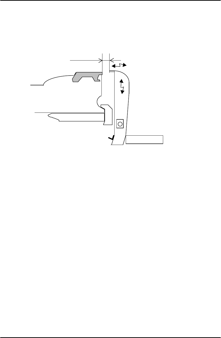
Waste tape duct height adjustment
1. Attach the waste tape duct and temporarily tighten it.
2. Load a feeder on the device table and set the Y direction clearance between the feeder
and the waste tape duct to 12.5mm. Please see the diagram below:
3. Set the height of the waste tape duct so that it is around 1mm higher than the feeder
upper surface. There should be sufficient clearance for the waste tape to feed down the
duct into the waste tape box without getting stuck.
4. To confirm that the waste tape duct is not skewed, check that the clearance and height
are the same at slot numbers 1 and 40.
Waste tape duct
Feeder
Approx. 12.5mm