xp141-241-341-5.0E.pdf - 第143页
FK-9F98- 29 XP Series training Text for Service Engineers Edition 5.0 XP241 – Chapter 5 Peripheral Adjustments Page 18 of 19 Fuji Machine Mfg. Co., Ltd. Okazaki. SMT Equipment Quality Assurance Dept . 5 – 18 CS Section 5…
FK-9F98-29 XP Series training Text for Service Engineers
Edition 5.0 XP241 – Chapter 5 Peripheral Adjustments Page 17 of 19
Fuji Machine Mfg. Co., Ltd. Okazaki.
SMT Equipment Quality Assurance Dept.
5 – 17 CS Section
5.5 Adjusting the nozzle/parts vacuum pressure sensor
Jig: Nozzle jig (Z9531DEPJ0070)
Measuring equipment: Manometer, (PG-100-02VH).
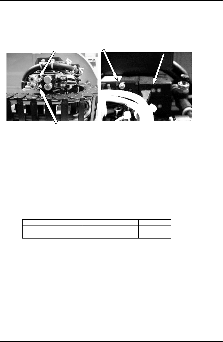
1. Refer to the picture above and turn the nozzle air blow speed controller 5 times from fully
closed and lock.
2. Enter I/O Y021 NozzleUnhold and adjust the blow time throttle so that the air blow is ON
for 2 seconds and then cuts out. Once the blow time is adjusted correctly, lock the
throttle.
Vacuum sensor setting
1. Switch both vacuum sensors from [MEAS] to [SET].
2. Adjust the “set” volume dial on the side of the sensor until the sensor displays the
following values:
Sensor Position Value
Nozzle Vacuum Sensor Top Sensor -20
Parts Vacuum Sensor Bottom Sensor -35
3. Once the values have been set switch both vacuum sensors from [SET] to [MEAS].
4. Turn I/O Y021 NozzleUnhold OFF when the nozzle jig is attached. The nozzle vacuum
sensor should show a value of –70Mpa or more negative.
5. Turn I/O Y020 PartsPickUp ON. The parts vacuum sensor should show –70Mpa or more
negative, when a part is vacuumed.
6. Attach the manometer to the nozzle jig. Turn Y021 NozzleUnhold OFF, and attach the
nozzle jig to the placing head. Turn I/O Y020 PartsPickUp ON. Under these conditions
the manometer should indicate the vaccuum pressure is –600mmHg (-79.99kPa) or more
negative.
7. Finally adjust the parts air blow speed controller. Turn Y01D PartsPickUpDes ON, and
Y020 PartsPickUp OFF, then adjust the speed controller until the manometer indicates
the air blow pressure is +50 mmHg (6.67kPa).
Parts air blow
Nozzle air blow
Blow time throttle Pressure setting trimmer (SET dial)
FK-9F98-29 XP Series training Text for Service Engineers
Edition 5.0 XP241 – Chapter 5 Peripheral Adjustments Page 18 of 19
Fuji Machine Mfg. Co., Ltd. Okazaki.
SMT Equipment Quality Assurance Dept.
5 – 18 CS Section
5.6 Adjusting the power remover
1. For details of how to set the amplifier for the power remover please refer to chapter 1.7.
2. Select [Maintenance C] – [Proper Data Editor] – [MACHINE_TYPE_2] and confirm that
the proper data item [Remover Type] is set to 1.
3. Set the power remover in its station.
4. Select [JOG] and inch the vacuum head close to the remover.
5. Press the emergency button to cut the 200V power supply to the servos. Lower the Z-axis
and stop just before it contacts the remover. Manually jog the position of the X and Y axes
until the pick up head is aligned directly above the remover.
6. Select [Maintenance C] – [Proper Data Editor] – [NOZZLE_POSITION] –
[X_RemoverPos] and [Y_RemoverPos] – [Direct Servo Input] to save the current X and Y
axes positions to proper data.
7. Lower the Z-axis until the pick-up head just contacts the top of the remover, then lower
the head a further 1.0mm. Select [Z_RemoverPos] – [Direct Servo Input] to save the
current Z axis position to proper data.
8. Release the emergency button, and turn the 200V supply to the servos ON. Select
[Production] – [Nozzle Operation] – [Remover] to pick up the remover.
9. Select [Maintenance A] – [I/O Check] – [Y030 RemoverVacuum] – [ON].
10. Confirm that the remover can vacuum a 750 gram tray.
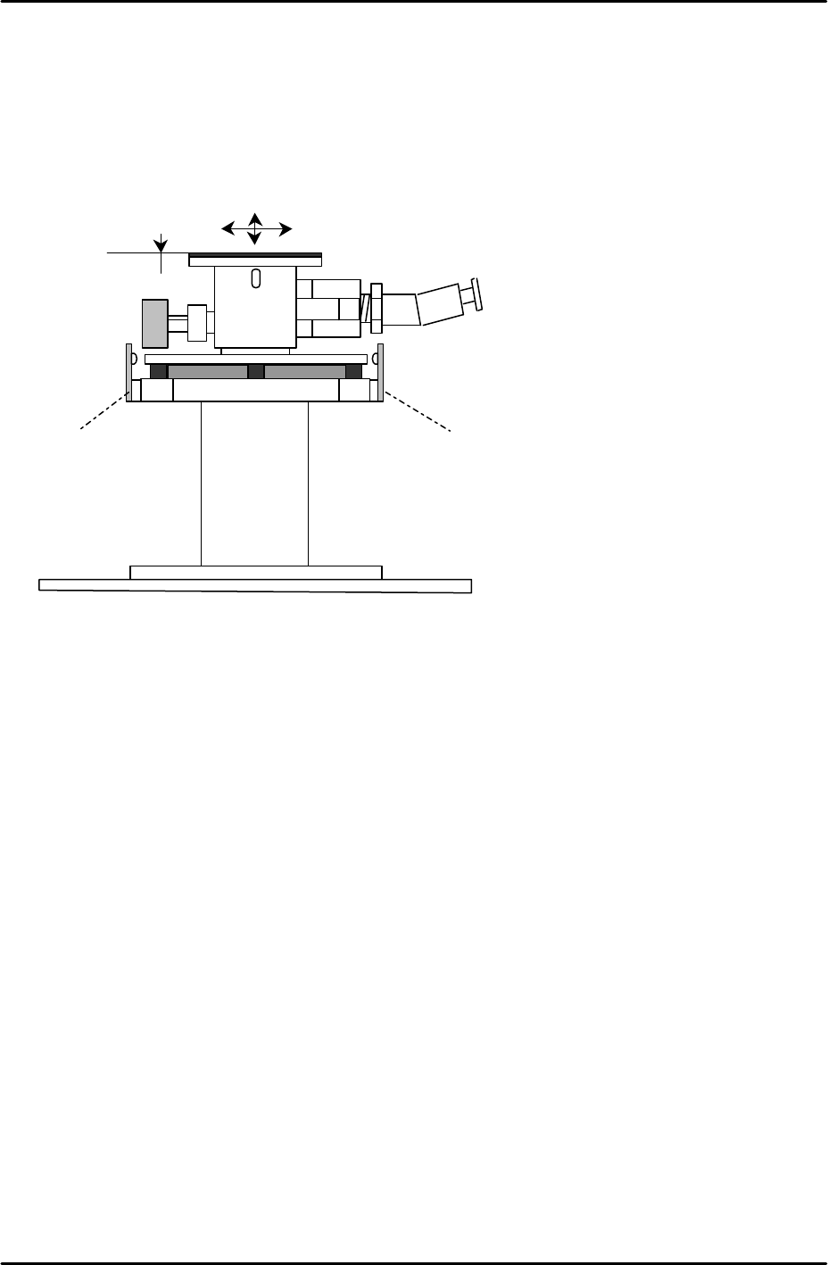
Set Check Sensor
Set Check Sensor

FK-9F98-29 XP Series training Text for Service Engineers
Edition 5.0 XP241 – Chapter 5 Peripheral Adjustments Page 19 of 19
Fuji Machine Mfg. Co., Ltd. Okazaki.
SMT Equipment Quality Assurance Dept.
5 – 19 CS Section
Power remover set check sensors
1. Select [Maintenance A] – [I/O Check] – [X029 Remover Set Check]. The I/O should be
ON when the power remover is set correctly in its pins, and OFF when set incorrectly.
The sensor beam is designed to be cut if the power remover is 1.5mm or more higher
than its correct position.