xp141-241-341-5.0E.pdf - 第149页
FK-9F98- 29 XP Series Training Text for Service Engineers Edition 5.0 XP241 – Chapter 6 Proper Data Measurements Page 3 of 20 Fuji Machine Mfg. Co., Ltd. Okazaki. SMT Equipment Quality Assurance Dept . 6 – 3 CS Section 6…
FK-9F98-29 XP Series Training Text for Service Engineers
Edition 5.0 XP241 – Chapter 6 Proper Data Measurements Page 2 of 20
Fuji Machine Mfg. Co., Ltd. Okazaki.
SMT Equipment Quality Assurance Dept.
6 – 2 CS Section
6. Select [Maintenance A] – [JOG] and [Fiducial]. The light comes ON for the mark
camera, and the raw image is displayed on the monitor.
7. Adjust the focus ring on the mark camera so that the markings on the plate jig come
into clear, sharp focus.
8. Lock the focus ring and apply adhesive (Loctite 425) to the lens lock hollow bolts.
9. Remove the light source unit.
10. Install the lens cover.
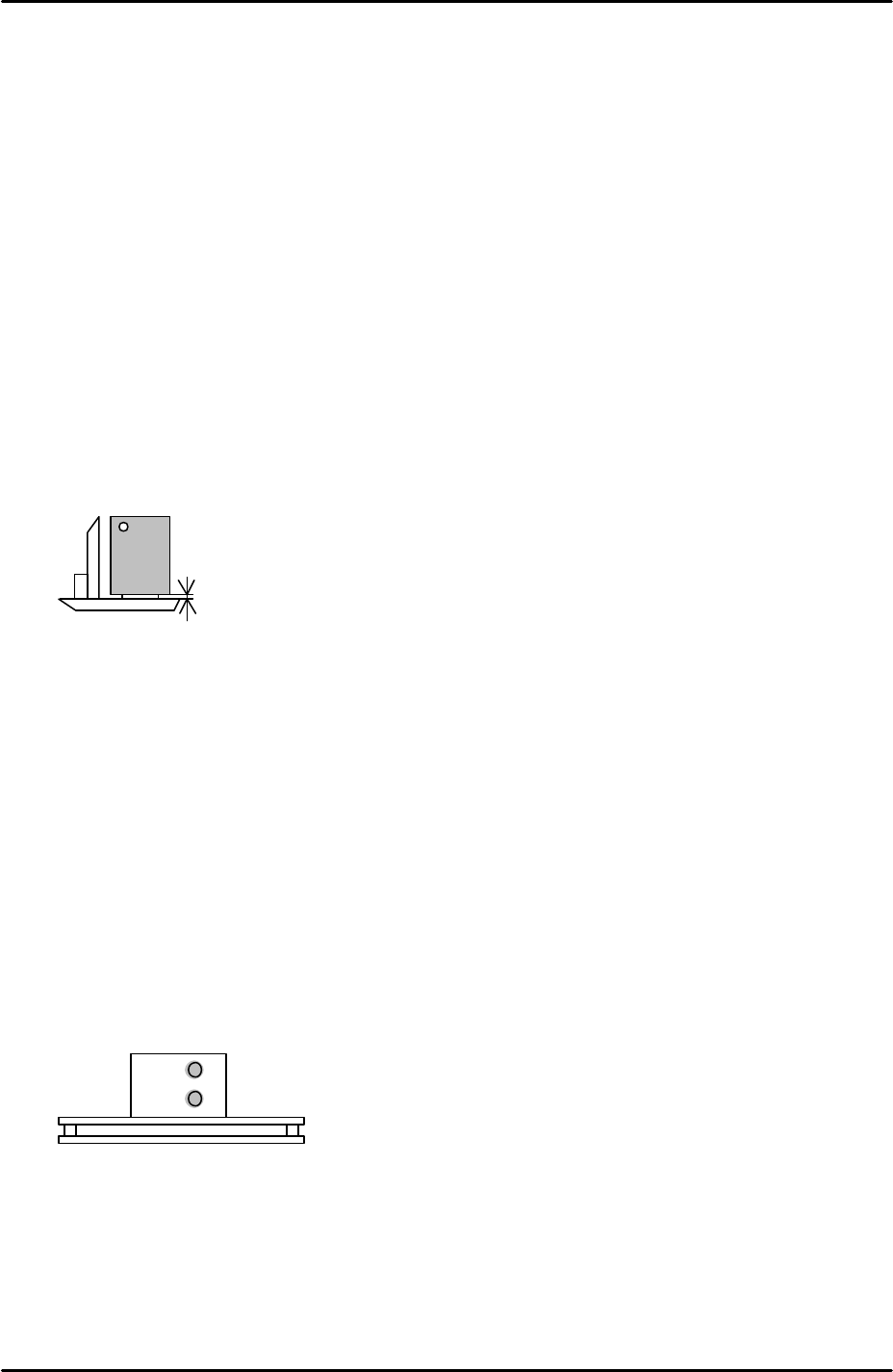
11. Replace the light source unit right up against the lip of the camera installation
bracket.
12. Set the position of the lens cover so that there is 0.5mm clearance between the
bottom of the lens cover and the top of the light source unit:
Camera Brightness Measurement
1. The lighting unit contains two different light sources. One (light source A) is the ring
of diodes at the bottom of the unit. The other (light source B) is the rectangular light
emitter found above the ring of diodes.
2. Place the color sample disc on the mark camera jig plate and bring the mark
camera above the disc.
3. Select [Maintenance A] – [Jog] – [Fiducial].
4. Confirm that the two LED lights for A and B are ON:
5. With the mark camera centered on the color sample disc touch the screen to display
a brightness reading.
6. Adjust the camera gain so that the brightness becomes around 120.
0.5mm
A
B
FK-9F98-29 XP Series Training Text for Service Engineers
Edition 5.0 XP241 – Chapter 6 Proper Data Measurements Page 3 of 20
Fuji Machine Mfg. Co., Ltd. Okazaki.
SMT Equipment Quality Assurance Dept.
6 – 3 CS Section
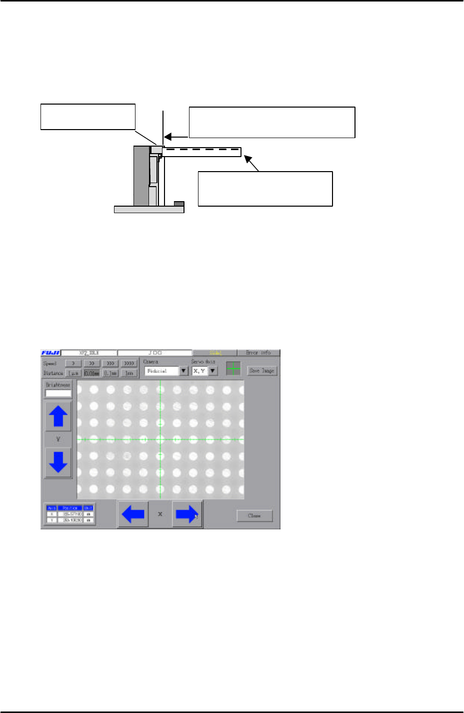
6. 2 Measuring the mark camera resolution
Equipment: Glass gage for mark camera resolution measurement (Z3502DFAJ0020).
1. Clamp the glass gage in the main table. Ensure it is flush with the reference rail.
2. Select [Maintenance A] – [Jog] – [Fiducial] to display the mark camera live image.
3. Bring the mark camera above the center of the glass gage and select the cross
hairs.
4. Inch the mark camera until it is centered on the center dot in the image (if the image
is too bright then ensure the emergency switch is pressed and then use your hand
to shade the mark camera until the dots on the glass gage become visible) :
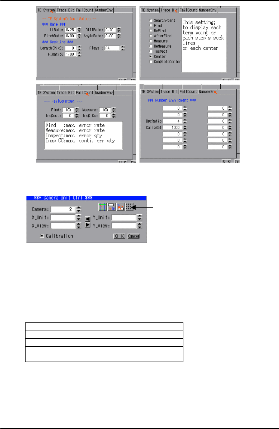
5. Select [Maintenance A] – [I/O Check] – [Y010 Fiducial Lamp] – ON.
6. Select [Program] – [Template editor] – and then right click on the screen to display a
menu box.
7. Select [Utility] – [Default Setting] and confirm that the default settings are identical
to those shown below:
The reference rail
Push the glass gauge against the
reference rail and clamp the gauge.
The glass gauge should be
printed side up.
FK-9F98-29 XP Series Training Text for Service Engineers
Edition 5.0 XP241 – Chapter 6 Proper Data Measurements Page 4 of 20
Fuji Machine Mfg. Co., Ltd. Okazaki.
SMT Equipment Quality Assurance Dept.
6 – 4 CS Section
8. Select [Utility] – [Scale Setting] – [Camera 2] – and click on the resolution
measurement tab:
9. Answer YES to the question “Set Center?” and the resolution measurement will
proceed.
10. Answer NO to the question “Do you save calibration data to FD?”
11. To the next question “Save Calibration Data?” answer YES.
12. Confirm that the resolution results are within the tolerances described below:
Mark camera resolution tolerances
X_Unit 0.017 ~ 0.0189
X_View 10.9 ~ 12.1
Y_Unit 0.017 ~ 0.0189
Y_View 8.16 ~ 9.07
13. The resolution calibration is now complete. Right click on the screen and select
return.
Resolution
Measurement