xp141-241-341-5.0E.pdf - 第151页
FK-9F98- 29 XP Series Training Text for Service Engineers Edition 5.0 XP241 – Chapter 6 Proper Data Measurements Page 5 of 20 Fuji Machine Mfg. Co., Ltd. Okazaki. SMT Equipment Quality Assurance Dept . 6 – 5 CS Section 6…
FK-9F98-29 XP Series Training Text for Service Engineers
Edition 5.0 XP241 – Chapter 6 Proper Data Measurements Page 4 of 20
Fuji Machine Mfg. Co., Ltd. Okazaki.
SMT Equipment Quality Assurance Dept.
6 – 4 CS Section
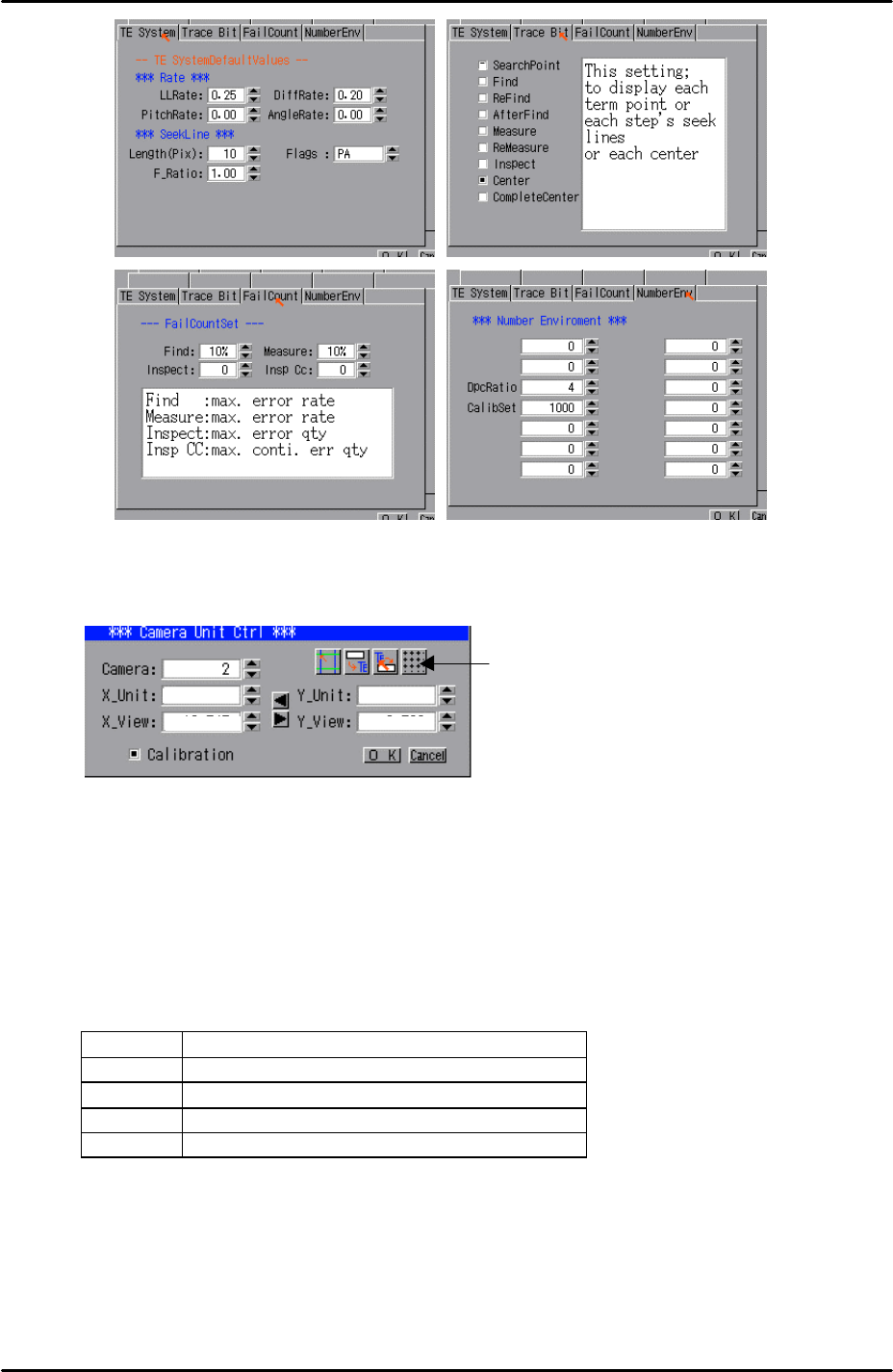
8. Select [Utility] – [Scale Setting] – [Camera 2] – and click on the resolution
measurement tab:
9. Answer YES to the question “Set Center?” and the resolution measurement will
proceed.
10. Answer NO to the question “Do you save calibration data to FD?”
11. To the next question “Save Calibration Data?” answer YES.
12. Confirm that the resolution results are within the tolerances described below:
Mark camera resolution tolerances
X_Unit 0.017 ~ 0.0189
X_View 10.9 ~ 12.1
Y_Unit 0.017 ~ 0.0189
Y_View 8.16 ~ 9.07
13. The resolution calibration is now complete. Right click on the screen and select
return.
Resolution
Measurement
FK-9F98-29 XP Series Training Text for Service Engineers
Edition 5.0 XP241 – Chapter 6 Proper Data Measurements Page 5 of 20
Fuji Machine Mfg. Co., Ltd. Okazaki.
SMT Equipment Quality Assurance Dept.
6 – 5 CS Section
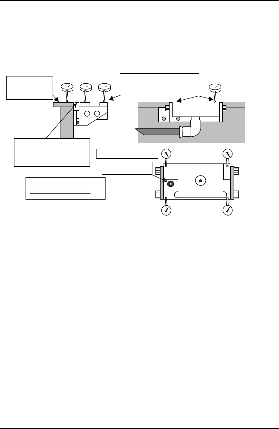
6.3 Measuring the mark camera orientation
Equipment: lever type dial gage (0.01mm).
1. Adjust the height of the glass gage station so that it is level with the reference rail
(tolerance +/- 0.05mm). Also ensure that the glass gage station is flat (tolerance
0.05mm).
2. Select [Maintenance A] – [JOG] – [Fiducial] and display the crosshairs on the
screen.
3. Inch the mark camera until it is centered on the fiducial mark on the left of the parts
gage station.
4. Select [Maintenance C] – [Mark camera Measurement] – [FMarkPos Measure] –
[START] – [Change mark position] – [Execute] to save the fiducial mark position.
5. Select [Angle Measure] to measure the mark camera orientation.
6. Select [X Unit measure] to measure the mark camera resolution. Note that this is
not the primary resolution measurement, therefore do not save the results. Check
that the resolution values are within 0.05mm of those recorded in step 6.2 and then
press cancel.
7. Select [Y Unit measure] to measure the mark camera resolution. Note that this is
not the primary resolution measurement therefore do not save the results. Check
that the resolution values are within 0.05mm of those recorded in step 6.2 and then
press cancel.
8. If the deviation between the resolution values recorded in steps 6.2 and 6.3 is more
than 0.05mm re-measure the resolution using the glass gage procedure described
in 6.2.
9. Note that 6.2 is the primary resolution measurement because it reads a whole
Set dial to “0” on
the top surface of
the reference rail.
Adjust the flatness to within
0.05mm in the 4 corners of the
glass gauge station.
Tolerance: for 4 corners of
the height within 0.05mm
Fiducial mark
Flatness: within 0.05mm
Adjust to within +/- 0.05mm
for the height of the reference
rail and parts gauge station.
FK-9F98-29 XP Series Training Text for Service Engineers
Edition 5.0 XP241 – Chapter 6 Proper Data Measurements Page 6 of 20
Fuji Machine Mfg. Co., Ltd. Okazaki.
SMT Equipment Quality Assurance Dept.
6 – 6 CS Section
series of marks on the glass gage and takes into account lens distortion.
10. Should the values in 6.2 and 6.3 fail to match within the tolerance after re-
measurement, please contact FUJI.
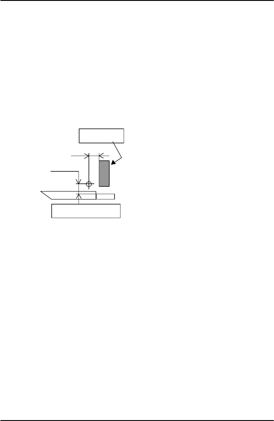
6.4 Measuring the board origin
1. Select [Maintenance A] – [I/O check] – [Y02A Main StationSt] – and raise the
main stopper.
2. Select [Maintenance A] – [JOG] – [Fiducial] and display the crosshairs on the
screen.
3. Set the vertical cross hair flush with the left side of the main stopper and then
use the inching tabs to move the X axis exactly 5mm in the minus direction.
4. Select [Maintenance C] – [Proper Data Editor] – [Machine Origin] – [X_board
Origin] and use direct servo input to save the current position to proper data.
5. Return to the [JOG] screen and set the horizontal cross hair flush with the side
of the reference rail and then use the inching tabs to move the Y axis 5.25mm
in the plus direction.
6. Select [Maintenance C] – [Proper Data Editor] – [Machine Origin] – [Y_board
Origin] and use direct servo input to save the current position to proper data.
6.5 Measuring Z0
Jig: plate jig (AJPJ0060).
Jig: nozzle jig (Z9531DEPJ0070).
1. Select [Maintenance A] – [I/O check] – [Y021 Nozzle UnHold] – [OFF] and
attach the nozzle jig.
2. Clamp the plate jig in the main conveyor.
3. Bring the nozzle jig above the plate jig and then press the emergency stop
button to cut the 200 volt power supply to the servos.
4. Manually descend the Z-axis until the nozzle jig contacts the plate jig surface.
5.0 mm
5.25 mm
Main Stopper
Side of the reference rail