xp141-241-341-5.0E.pdf - 第154页
FK-9F98- 29 XP Series Training Text for Service Engineers Edition 5.0 XP241 – Chapter 6 Proper Data Measurements Page 8 of 20 Fuji Machine Mfg. Co., Ltd. Okazaki. SMT Equipment Quality Assurance Dept . 6 – 8 CS Section 3…
FK-9F98-29 XP Series Training Text for Service Engineers
Edition 5.0 XP241 – Chapter 6 Proper Data Measurements Page 7 of 20
Fuji Machine Mfg. Co., Ltd. Okazaki.
SMT Equipment Quality Assurance Dept.
6 – 7 CS Section
5. Select [Maintenance C] – [Proper data editor] – [Machine Origin] – [Z_board
surface] and use direct servo input to save the current position in proper data.
6.6 Adjusting the parts camera
Note: the adjustment procedure is the same for both the front and rear cameras.
Prism measurement
1. Detach the light source from the prism.
2. Use a dial gage to check if the prism is parallel to the X-axis. The factory tolerance
is 0.02mm/65mm. If outside of this range adjust the prism position relative to the X-
axis.
3. Measure the flatness of the prism top surface. This is non-adjustable, so if the
value is outside the tolerance of 0.01mm, please contact FUJI.
4. Replace the light source in the center of the prism.
Camera settings
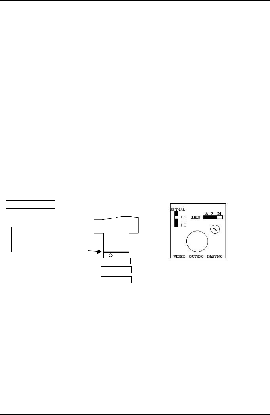
1. Set the signal, gain and aperture as shown in the following table and diagram:
SIGNAL 1N
GAIN M
Aperture 6
Note: Ensure the lens unit attachment is fastened with adhesive (Loctite 425).
Note: If attaching the camera unit to the camera installation bracket, tighten the bolts
with 0.5Nm torque and apply adhesive.
Note: Confirm there is a 1mm collar inserted in the front camera attachment as
indicated in the diagram above.
Camera focus
1. Select [Maintenance A] – [I/O check] – [Y021 Nozzle UnHold] – [OFF] and attach
the nozzle jig to the placing head.
2. Select [Maintenance A] – [Jog] – and select “side1 front” or “side 2 front” to
display the live image on the screen.
*Ensure a 1 mm collar is
inserted in the attachment
section of camera 3 (front).
Top view of the camera
FK-9F98-29 XP Series Training Text for Service Engineers
Edition 5.0 XP241 – Chapter 6 Proper Data Measurements Page 8 of 20
Fuji Machine Mfg. Co., Ltd. Okazaki.
SMT Equipment Quality Assurance Dept.
6 – 8 CS Section
3. Bring the nozzle above the center of the prism and set the Z-axis to the part
inspection height: (Z0 + 27.5mm).
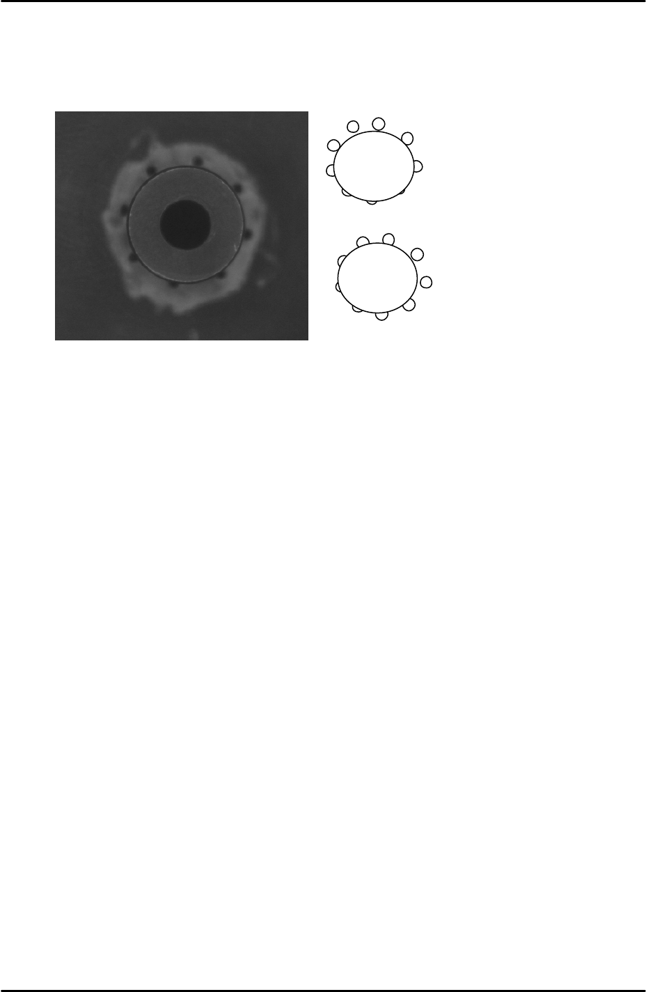
4. To check the tilt of the camera ensure that the holes around the nozzle jig are
evenly balanced as shown in the picture below:
5. If the holes are unbalanced in the Y direction adjust the rear prism orientation
(this is the smaller of the two prisms).
6. If the holes are unbalanced in the X direction adjust the camera tilt.
7. Confirm that the Z-axis is still at the part inspection height (Z0 +27.5mm).
8. To adjust the focus rotate the focus ring until the end of the nozzle jig comes into
clear, sharp, focus. Alternatively a component may be placed on the end of the
nozzle jig but in this case remember the Z-axis height should be raised by the
equivalent of the component height (Z0 + 27.5mm + component height).
9. Once the focus has been set tighten the focus ring hollow bolt and apply
adhesive (Loctite 425).
Camera center
1. Select [Maintenance A] – [Jog] – and select “side1 front” or “side 2 front” to
display the live image on the screen.
2. Select the cross hairs.
3. Bring the nozzle center to the center of the vertical cross hair by loosening the
X-direction bolts on the rear of the camera and sliding the camera in the X-
direction.
4. For the Y-axis use a scale to find the center of the prism light source and set the
nozzle jig directly above this position. If, at this position, the nozzle center is not
roughly in the center of the horizontal cross hair loosen the Y-direction bolts on
the rear prism and slide the prism in the Y direction until the nozzle center and
camera center match.
= Prism
= Camera

FK-9F98-29 XP Series Training Text for Service Engineers
Edition 5.0 XP241 – Chapter 6 Proper Data Measurements Page 9 of 20
Fuji Machine Mfg. Co., Ltd. Okazaki.
SMT Equipment Quality Assurance Dept.
6 – 9 CS Section
Prism position
1. Select [Maintenance A] – [Jog] – and select “side1 front” or “side 2 front” to display
the live image on the screen.
2. Display the cross hairs on the screen.
3. Inch the Y-axis until the nozzle is in the center of the cross hairs.
4. Record the counter value at this position.
5. Select [Maintenance C] – [Proper Data Editor] – [Prism Position] – [Prism
front/Prism back] and manually input the Y counter value. Note that the direct servo
input option is not available for this proper data item.
Brightness adjustment
1. Select [Maintenance A] – [I/O Check] – [Y021 Nozzle Unhold] – [OFF] and attach a
15mm or 20mm nozzle to the placing head.
2. Select [Maintenance A] – [I/O Check] – [Y020 Parts Pickup] – [ON] and attach the
color sample disc to the nozzle.
3. Bring the color sample disc into the camera’s field of view and set the Z-axis counter
to the vision processing height: Z0 + 27.5 + 0.5mm (0.5mm represents the thickness
of the color sample disc).
4. Touch the image on the screen to measure the current brightness value.
5. Set the brightness value to 120 by turning the gain adjusting screw on the top of the
parts camera.
6. The brightness value will vary slightly at different points on the color sample image,
therefore set the average value to 120.
6.7 Measuring the parts camera resolution
1. Equipment: glass gage for resolution measurement (Z3502DFAJ002). Nozzle jig
(Z9531DEPJ0070).
2. Select [Maintenance A] – [I/O Check] – [Y021 Nozzle Unhold] – [OFF] and attach the
nozzle jig to the placement head.
3. Select [Maintenance A] – [I/O check] – [Y020 Parts Pickup] – [ON] and attach the
glass gage to the nozzle jig.
4. Note that the two surfaces of the glass gage are not identical. The glass gage
should be attached to the nozzle jig with the printed surface facing downwards.
5. Bring the glass gage to the prism position and raise it to the vision processing
height: Z0 + 27.5 + 2.5mm (2.5mm is equivalent to the thickness of the glass gage).