xp141-241-341-5.0E.pdf - 第156页
FK-9F98- 29 XP Series Training Text for Service Engineers Edition 5.0 XP241 – Chapter 6 Proper Data Measurements Page 10 of 20 Fuji Machine Mfg. Co., Ltd. Okazaki. SMT Equipment Quality Assurance Dept . 6 – 10 CS Section…

FK-9F98-29 XP Series Training Text for Service Engineers
Edition 5.0 XP241 – Chapter 6 Proper Data Measurements Page 9 of 20
Fuji Machine Mfg. Co., Ltd. Okazaki.
SMT Equipment Quality Assurance Dept.
6 – 9 CS Section
Prism position
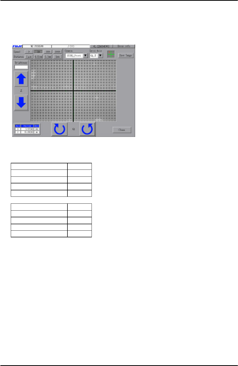
1. Select [Maintenance A] – [Jog] – and select “side1 front” or “side 2 front” to display
the live image on the screen.
2. Display the cross hairs on the screen.
3. Inch the Y-axis until the nozzle is in the center of the cross hairs.
4. Record the counter value at this position.
5. Select [Maintenance C] – [Proper Data Editor] – [Prism Position] – [Prism
front/Prism back] and manually input the Y counter value. Note that the direct servo
input option is not available for this proper data item.
Brightness adjustment
1. Select [Maintenance A] – [I/O Check] – [Y021 Nozzle Unhold] – [OFF] and attach a
15mm or 20mm nozzle to the placing head.
2. Select [Maintenance A] – [I/O Check] – [Y020 Parts Pickup] – [ON] and attach the
color sample disc to the nozzle.
3. Bring the color sample disc into the camera’s field of view and set the Z-axis counter
to the vision processing height: Z0 + 27.5 + 0.5mm (0.5mm represents the thickness
of the color sample disc).
4. Touch the image on the screen to measure the current brightness value.
5. Set the brightness value to 120 by turning the gain adjusting screw on the top of the
parts camera.
6. The brightness value will vary slightly at different points on the color sample image,
therefore set the average value to 120.
6.7 Measuring the parts camera resolution
1. Equipment: glass gage for resolution measurement (Z3502DFAJ002). Nozzle jig
(Z9531DEPJ0070).
2. Select [Maintenance A] – [I/O Check] – [Y021 Nozzle Unhold] – [OFF] and attach the
nozzle jig to the placement head.
3. Select [Maintenance A] – [I/O check] – [Y020 Parts Pickup] – [ON] and attach the
glass gage to the nozzle jig.
4. Note that the two surfaces of the glass gage are not identical. The glass gage
should be attached to the nozzle jig with the printed surface facing downwards.
5. Bring the glass gage to the prism position and raise it to the vision processing
height: Z0 + 27.5 + 2.5mm (2.5mm is equivalent to the thickness of the glass gage).
FK-9F98-29 XP Series Training Text for Service Engineers
Edition 5.0 XP241 – Chapter 6 Proper Data Measurements Page 10 of 20
Fuji Machine Mfg. Co., Ltd. Okazaki.
SMT Equipment Quality Assurance Dept.
6 – 10 CS Section
6. Select [Maintenance A] – [Jog] – [Side1front/side2front] – and display the cross hairs
on the screen.
7. Set the center of the cross hairs in the center of one of the glass gage dots, as
shown in the picture below:
8. Select [Maintenance A] – [I/O Check] – and depending on which camera you are
adjusting set the following I/Os:
Front camera I/O
Y00C StroboTrigger ON
Y00D StroboLampA ON
Y00E StroboLampB ON
Y00F StroboCharge ON
Rear camera I/O
Y00C StroboTrigger ON
Y00D StroboLampA ON
Y00E StroboLampB OFF
Y00F StroboCharge ON
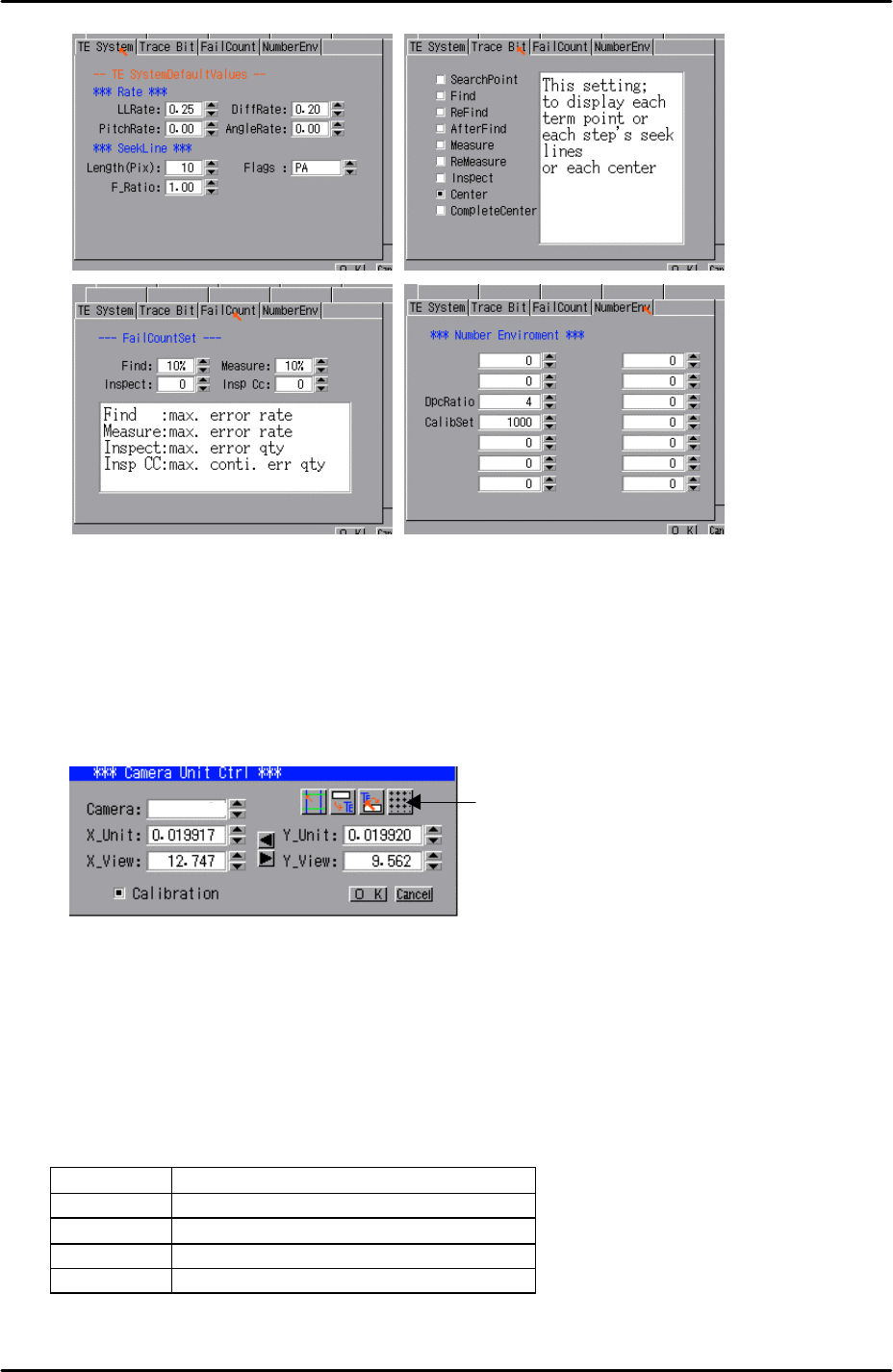
Default settings
1. Select [Program] – [Template Editor] – then right click on the screen to display a
menu box.
2. Select [Utility] – [Default settings] and confirm that the default settings are identical
to those in the following picture, note that the default settings are the same for the
mark camera and both parts cameras:
FK-9F98-29 XP Series Training Text for Service Engineers
Edition 5.0 XP241 – Chapter 6 Proper Data Measurements Page 11 of 20
Fuji Machine Mfg. Co., Ltd. Okazaki.
SMT Equipment Quality Assurance Dept.
6 – 11 CS Section
Resolution measurement
1. Select [Utility] – [Scale Setting] – [Camera 3] or [Camera 4] depending on which
camera you are adjusting. “Camera 3” is the side 1 camera. “Camera 4” is the side
2 camera.
2. Click on the resolution measurement tab:
3. Answer YES to the question “Set Center?” and the resolution measurement will
proceed.
4. Answer NO to the question “Do you save calibration data to FD?”
5. To the next question, “Save calibration data?” answer YES?
6. Confirm that the resolution results are within the tolerances described below:
Front camera resolution tolerance
X_Unit 0.052 ~ 0.055
X_View 33.00 ~ 35.00
Y_Unit 0.052 ~ 0.055
Y_View 24.80 ~ 26.20
Resolution
Measurement
3