xp141-241-341-5.0E.pdf - 第162页
FK-9F98- 29 XP Series Training Text for Service Engineers Edition 5.0 XP241 – Chapter 6 Proper Data Measurements Page 16 of 20 Fuji Machine Mfg. Co., Ltd. Okazaki. SMT Equipment Quality Assurance Dept . 6 – 16 CS Section…
FK-9F98-29 XP Series Training Text for Service Engineers
Edition 5.0 XP241 – Chapter 6 Proper Data Measurements Page 15 of 20
Fuji Machine Mfg. Co., Ltd. Okazaki.
SMT Equipment Quality Assurance Dept.
6 – 15 CS Section
Large parts reject position
1. Equipment: Nozzle jig (Z95314DEPJ0070)
2. Select [Maintenance A] – [I/O check] – [Y021 NozzleUnhold] – [OFF] and attach the
nozzle jig to the placing head.
3. Select [Maintenance A] – [Jog] – and carefully inch the nozzle jig above the surface
of the reject parts tray.
4. Press the emergency stop button to cut the 200 volt power supply to the servos and
then manually descend the Z-axis until the nozzle jig contacts the surface of the
reject parts tray.
5. Select [Maintenance C] – [Proper data editor] – [Dispose position] – [Z_Disposal 2]
– [Direct servo input] to save the current Z-axis position in proper data.
6. In the case of the reject parts tray the machine software determines the position of
X and Y disposal, so the “X_Disposal 2” and “Y_Disposal 2” entries should be set to
0 by default.
6.12 Measuring the tray parts pick up position
1. Equipment: Nozzle jig (Z95361DEPJ0070). Tray pick up measurement jig
(Z9531DEPJ0040).
2. Select [Manual Operation] – [Tray Operation] – [01, 02] – [Move Elevator] –
[START] – [Advance Shuttle] – [START] to bring tray 1 to the end of the U axis.
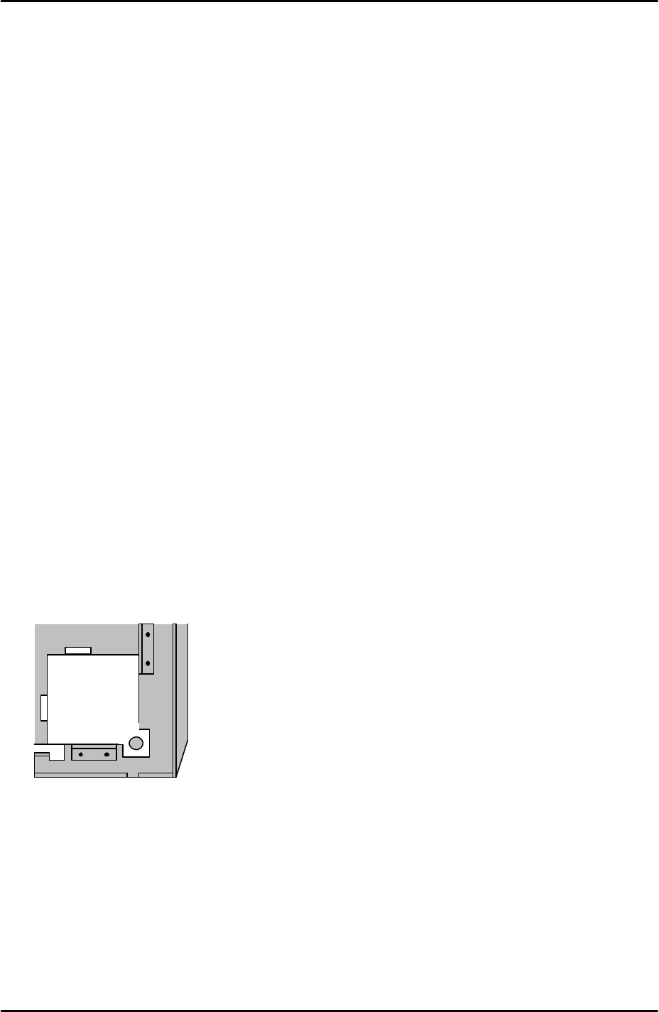
3. Set the tray pick up position jig in the front right corner of the tray as illustrated in
the following diagram:
4. Use magnets to secure the tray pick up jig in the corner of the tray.
5. Select [Maintenance A] – [I/O Check] – [Y021 NozzleUnhold] – [OFF] and attach
the nozzle jig to the placing head.
6. Bring the placing head over the tray pick up measurement jig and then press the
emergency stop button to cut the 200V power supply to the servos.
7. Manually move the X, Y and Z axes until the nozzle jig can slide smoothly into the
tray pick up position jig hole.
FK-9F98-29 XP Series Training Text for Service Engineers
Edition 5.0 XP241 – Chapter 6 Proper Data Measurements Page 16 of 20
Fuji Machine Mfg. Co., Ltd. Okazaki.
SMT Equipment Quality Assurance Dept.
6 – 16 CS Section
8. Select [Maintenance C] – [Proper data editor] – [Machine Origin] –
[X_stage2Org/Y_stage2Org] – [Direct servo input] to save the current X and Y axes
positions in proper data.
9. Remove the tray pick up position jig and descend the Z-axis until the nozzle jig
contacts the surface of tray 01.
10. Select [Maintenance C] – [Proper data editor] – [Machine Origin] –
[Z_stage2surface] – [Direct servo input] to save the current Z-axis position in proper
data.
11. After completing this adjustment select [Maintenance C] – [Proper data editor] –
[Operation] – and confirm that the proper data item “TrayDetectMotion” is set to 2.
6.13 Measuring the MFU pick up position
1. Equipment: Nozzle jig (Z9531DEPJ0070). MFU pick up position measurement jig
(Z5531ADPEPJ9010).
2. Select [Manual Operation] – [MFU Clamp] to clamp the MFU to the machine.
3. Mount the MFU pick up position measurement jig at device position 25.
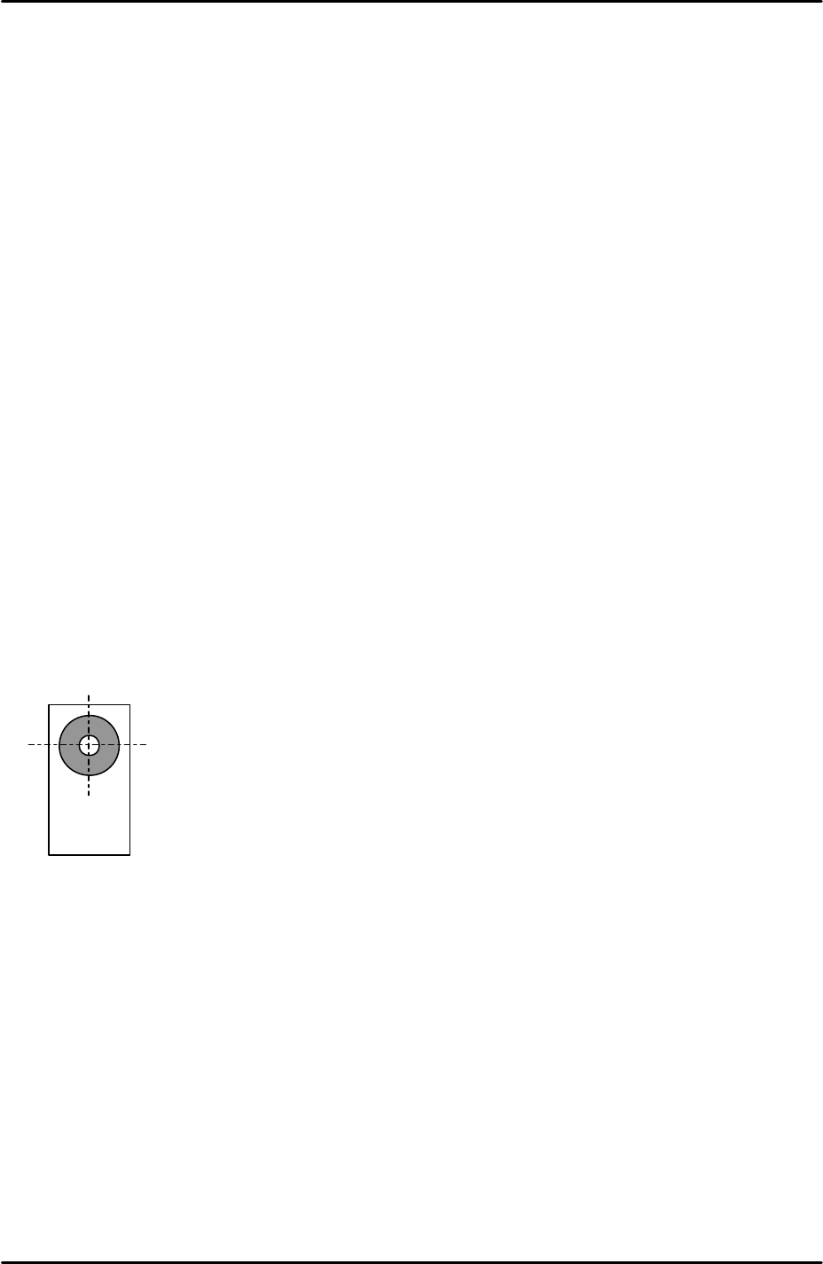
4. Select [Maintenance A] – [Jog] – [Fiducial] and display the cross hairs on the
screen.
5. Inch the X and Y axes until the fiducial camera cross hairs are centered on the XY
pick up position jig mark.
6. Select [Maintenance C] – [Proper data editor] – [Machine Origin] –
[X_Stage1Org/Y_Stage1Org] – [Direct servo input] to save the current X and Y
axes positions in proper data.
7. Select [Maintenance A] – [I/O Check] – [Y021 NozzleUnhold] – [OFF] and attach
the nozzle jig to the placing head.
8. Manually bring the nozzle jig above the surface of the MFU pick up position
measurement jig surface and descend the Z axis until the nozzle jig contacts the
surface.
9. Select [Maintenance C] – [Proper data editor] – [Machine Origin] –
[Z_Stage1surface] – [Direct servo input] to save the current Z-axis position in
proper data.
10. In situations where the MFU pick up position measurement jig is unavailable, a
normal feeder may be used. In this case align the fiducial camera center on the
Z5531ADPEPJ9010
FK-9F98-29 XP Series Training Text for Service Engineers
Edition 5.0 XP241 – Chapter 6 Proper Data Measurements Page 17 of 20
Fuji Machine Mfg. Co., Ltd. Okazaki.
SMT Equipment Quality Assurance Dept.
6 – 17 CS Section
component in the parts pick up cavity and save the X and Y positions in proper data
by following the procedure above. Set the Z_Stage1surface proper data where a
0.7 diameter nozzle first contacts the component surface.
6.14 Measuring the glass gage position
1. Equipment: Nozzle jig (Z9531DEPJ0070). Glass gage (BVDZ-0140).
2. Select [Maintenance A] – [Jog] – [Fiducial] – and display the cross hairs on the
screen.
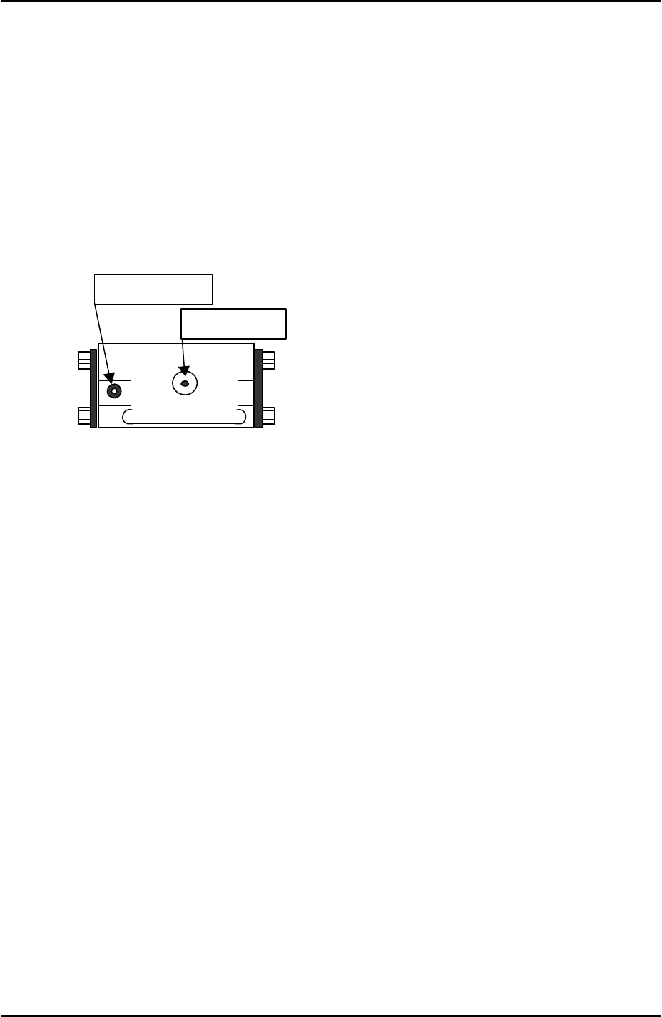
3. Inch the X and Y axes until the fiducial camera is centered on the glass gage
station vacuum hole.
4. Select [Maintenance C] – [Proper data editor] – [Jig Position] – [X_Jig Pick Pos1/
Y_Jig Pick Pos] – [Direct servo input] to save the current X and Y axes positions in
proper data.
5. Select [Maintenance A] – [I/O Check] – [Y021 NozzleUnhold] – [OFF] and attach
the nozzle jig to the placing head.
6. Set the glass gage in the glass gage station and inch the nozzle jig above the glass
gage.
7. Press the emergency stop button to cut the 200-volt power supply to the servos and
then manually lower the Z-axis until the nozzle jig contacts the surface of the glass
gage.
8. Select [Maintenance C] – [Proper data editor] – [Jig position] – [Z_Jig Pick Pos] –
[Direct servo input] to save the current Z-axis position in proper data.
Fiducial Mark
Vacuum hole