xp141-241-341-5.0E.pdf - 第164页
FK-9F98- 29 XP Series Training Text for Service Engineers Edition 5.0 XP241 – Chapter 6 Proper Data Measurements Page 18 of 20 Fuji Machine Mfg. Co., Ltd. Okazaki. SMT Equipment Quality Assurance Dept . 6 – 18 CS Section…
FK-9F98-29 XP Series Training Text for Service Engineers
Edition 5.0 XP241 – Chapter 6 Proper Data Measurements Page 17 of 20
Fuji Machine Mfg. Co., Ltd. Okazaki.
SMT Equipment Quality Assurance Dept.
6 – 17 CS Section
component in the parts pick up cavity and save the X and Y positions in proper data
by following the procedure above. Set the Z_Stage1surface proper data where a
0.7 diameter nozzle first contacts the component surface.
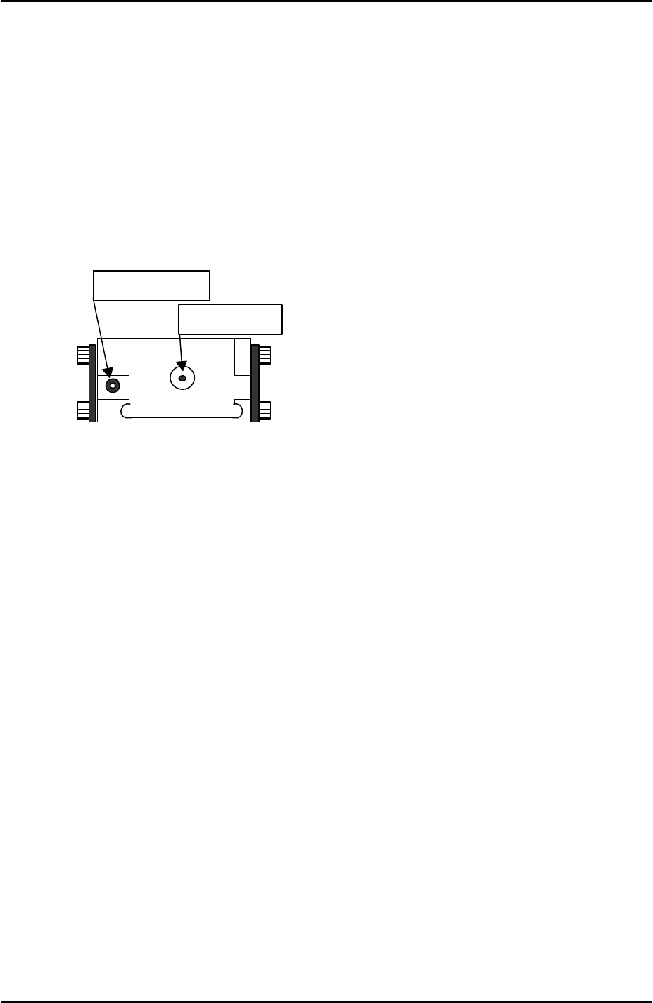
6.14 Measuring the glass gage position
1. Equipment: Nozzle jig (Z9531DEPJ0070). Glass gage (BVDZ-0140).
2. Select [Maintenance A] – [Jog] – [Fiducial] – and display the cross hairs on the
screen.
3. Inch the X and Y axes until the fiducial camera is centered on the glass gage
station vacuum hole.
4. Select [Maintenance C] – [Proper data editor] – [Jig Position] – [X_Jig Pick Pos1/
Y_Jig Pick Pos] – [Direct servo input] to save the current X and Y axes positions in
proper data.
5. Select [Maintenance A] – [I/O Check] – [Y021 NozzleUnhold] – [OFF] and attach
the nozzle jig to the placing head.
6. Set the glass gage in the glass gage station and inch the nozzle jig above the glass
gage.
7. Press the emergency stop button to cut the 200-volt power supply to the servos and
then manually lower the Z-axis until the nozzle jig contacts the surface of the glass
gage.
8. Select [Maintenance C] – [Proper data editor] – [Jig position] – [Z_Jig Pick Pos] –
[Direct servo input] to save the current Z-axis position in proper data.
Fiducial Mark
Vacuum hole
FK-9F98-29 XP Series Training Text for Service Engineers
Edition 5.0 XP241 – Chapter 6 Proper Data Measurements Page 18 of 20
Fuji Machine Mfg. Co., Ltd. Okazaki.
SMT Equipment Quality Assurance Dept.
6 – 18 CS Section
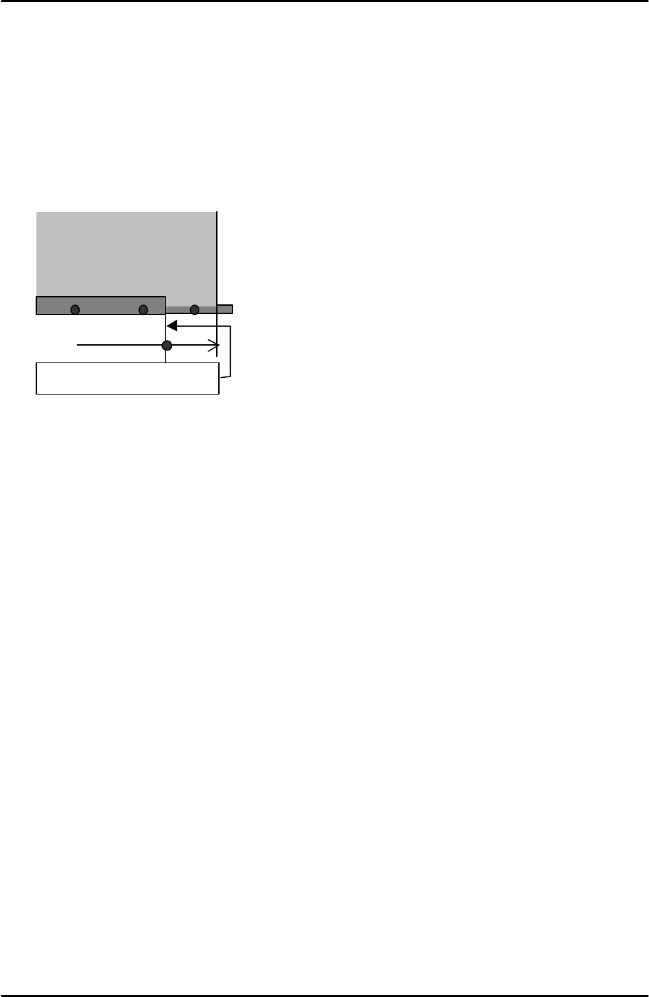
6.15 Measuring the matrix data
1. Equipment: glass gage for matrix measurement (A5704DEAJ14013).
2. Note that the matrix data measurement should be carried out when the machine is
cold, otherwise the results will not be reliable. Fuji recommends that the machine is
not used for at least two hours prior to the measurement.
3. Clamp the matrix measurement glass gage approximately 70mm from the main
conveyor right end.
4. Because the glass gage is 5mm thick the main lifter upper limit sensor will not come
ON when the gage is clamped. As a result it is necessary to interrupt the upper
limit sensor with a piece of paper tape.
5. Select [Maintenance A] – [Jog] – [Fiducial] – and display the cross hairs on the
screen.
6. Center the fiducial camera on the last dot in the bottom left hand corner of the glass
gage and record the Y-axis counter value.
7. Move the fiducial camera until it is centered on the last dot in the bottom right hand
corner of the glass gage. Compare the current Y-axis counter value with that
recorded in step 6. The difference in value should be within 0.5mm. This ensures
that the X-axis and the glass gage are parallel.
8. With the fiducial camera still centered on the last dot in the bottom right hand corner
of the glass gage select [Maintenance C] – [Matrix data measurement] – and set
the acceleration rate to 1.0 before selecting [Start].
9. The measurement will take approximately 1 hour to complete. Matrix data
measurement is designed to compensate for minute discrepancies in the
straightness of the X and Y- axis ball screws. The measurement is performed in
the factory prior to machine shipment and is not normally performed again.
6.16 Adjusting the conveyor automatic width changer
1. Equipment: lever type dial gage (0.01mm). Width defining mark bracket height
adjustment jig (A9531DEPJ1250).
2. Set the jig adjacent to the width defining mark bracket on the adjustable rail.
Glass gauge for matrix data
(A5704DEAJ1013)
Approx. 70mm
Main conveyor right end
FK-9F98-29 XP Series Training Text for Service Engineers
Edition 5.0 XP241 – Chapter 6 Proper Data Measurements Page 19 of 20
Fuji Machine Mfg. Co., Ltd. Okazaki.
SMT Equipment Quality Assurance Dept.
6 – 19 CS Section
3. Set the dial gage to 0 on the reference side of the jig and slide it across the width
defining mark bracket.
4. Adjust the height of the bracket so that it is the same height as the jig (tolerance +/-
0.05mm). The flatness of the bracket should be within 0.05mm.
5. Set the conveyor width to approximately 100mm.
6. Select [Maintenance A] – [Jog] – [Fiducial] – and display the cross hairs on the
screen.
7. Center the fiducial camera on the glass gage station fiducial mark and record the X-
axis counter value at this position.
8. Inch the fiducial camera in the Y direction until the width defining bracket comes
into view, then center the camera on the width defining mark.
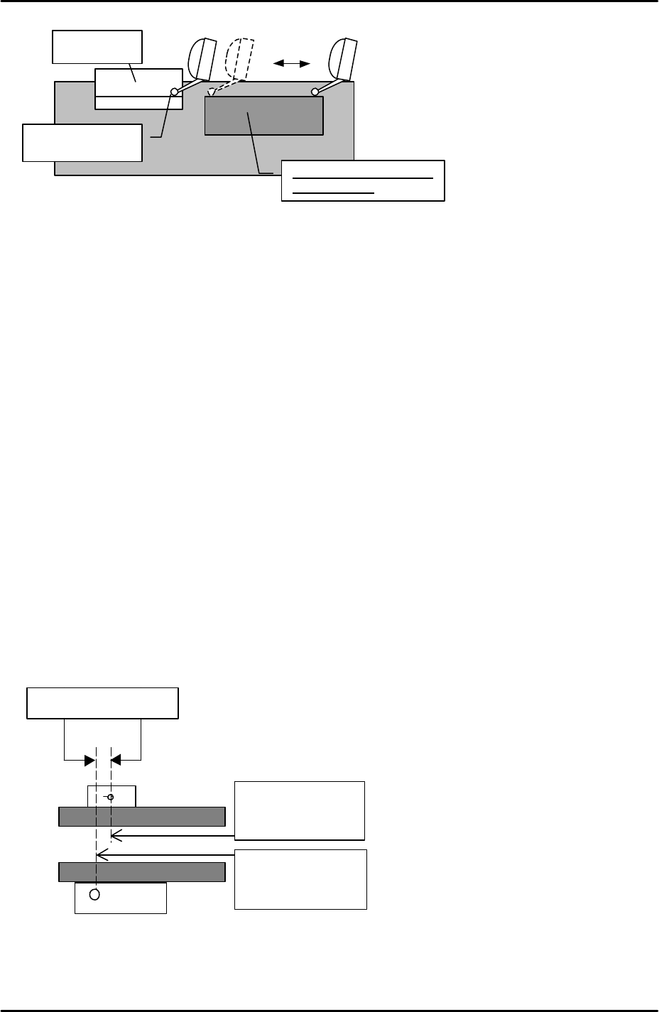
9. Record the X-axis counter value at this position and subtract this figure from the X
axis counter value recorded in step 7. This value is the “ConvWidthMarkDiffX”
proper data.
10. Select [Maintenance C] – [Proper data editor] – [Others] – [ConvWidthMarkDiffX] –
and manually input the figure calculated at step 9.
11. In the following example the ConvWidthMarkDiffX would be 1mm:
12. Set the conveyor width to minimum, then select [Production] – [Conveyor Width] –
[Measure Speed] – [START]. After the calibration is complete press [YES] to save
the results in proper data (ConvWidthMtrSpeed).
Height jig
Set the dial to “0”
Flatness
s
ho
u
ld be
within 0.05mm
X-axis counter:
135.000 mm
X-axis counter:
136.000 mm
ConvWidthMarkDiffX