xp141-241-341-5.0E.pdf - 第167页
C C h h a a p p t t e e r r 7 7 O O p p e e r r a a t t i i o o n n a a n n d d A A c c c c u u r r a a c c y y
FK-9F98-29 XP Series Training Text for Service Engineers
Edition 5.0 XP241 – Chapter 6 Proper Data Measurements Page 20 of 20
Fuji Machine Mfg. Co., Ltd. Okazaki.
SMT Equipment Quality Assurance Dept.
6 – 20 CS Section
13. Once speed measurement is complete input a board width and select [Move] –
[START]. The conveyor automatically moves to this board width.
14. Select a board with the same width as that input in step 13 and place it in the
conveyor. The board should fit smoothly into the conveyor, and there should be a
clearance of 0.5mm between conveyor and board. If not it is necessary to measure
an offset.
15. Use the conveyor width changer inching tabs to change the conveyor width until the
clearance between board and conveyor is 0.5mm then select [Measure Offset].
After the calibration is complete press [YES] to save the results in proper data
(ConvWidthOffset).
6.17 Corner dog adjustment
1. Select [Maintenance C] – [Proper data editor] – [Machine Type] – [CornerRearSide]
and set the corner dog proper data as described in the following table:
CornerRearSide
0 The corner dog is bypassed
1 The corner dog is square
2 The corner dog is round
2. Select [Maintenance C] – [Corner dog adjustment] – [Acquire Image] – [Start] and
the side 2 camera will acquire the corner dog image.
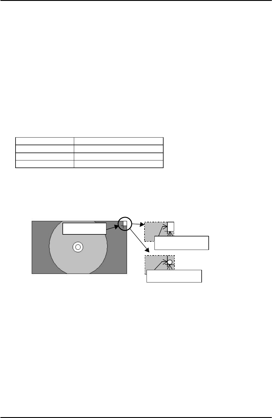
3. Adjust the position of the corner dog so that it aligns with the green cross hairs as
illustrated in the following diagram:
4. After aligning the corner dog with the green cross hairs select [Vision Test] and the
MS algorithm vision system will process the corner dog image. If the position of the
corner dog is within tolerance, seek lines will be drawn around the corner dog
edges and the vision test is a success. Should seek lines fail to appear readjust the
position of the corner dog and try again.
5. If after readjustment the seek lines still fail to appear it may be necessary to replace
the corner dog.
Corner dog
Round corner dog:
Align to the crosshair.
Square corner dog:
Align to the crosshair.

C
C
h
h
a
a
p
p
t
t
e
e
r
r
7
7
O
O
p
p
e
e
r
r
a
a
t
t
i
i
o
o
n
n
a
a
n
n
d
d
A
A
c
c
c
c
u
u
r
r
a
a
c
c
y
y
FK-9F98-29 XP Series Training Text for Service Engineers
Edition 5.0 XP241 – Chapter 7 Checking Operation and Accuracy Page 1 of 4
Fuji Machine Mfg. Co., Ltd. Okazaki
SMT Equipment Quality Assurance Dept.
7–1 CS Section
Chapter 7 – Checking Operation and Accuracy
7.1 Checking idle operation
1. Transmit the idle program “XP2_IDLE” to the machine.
2. Select [Production] – [Select Program] – [XP2_IDLE] – [Download] to bring the program
into the machine foreground.
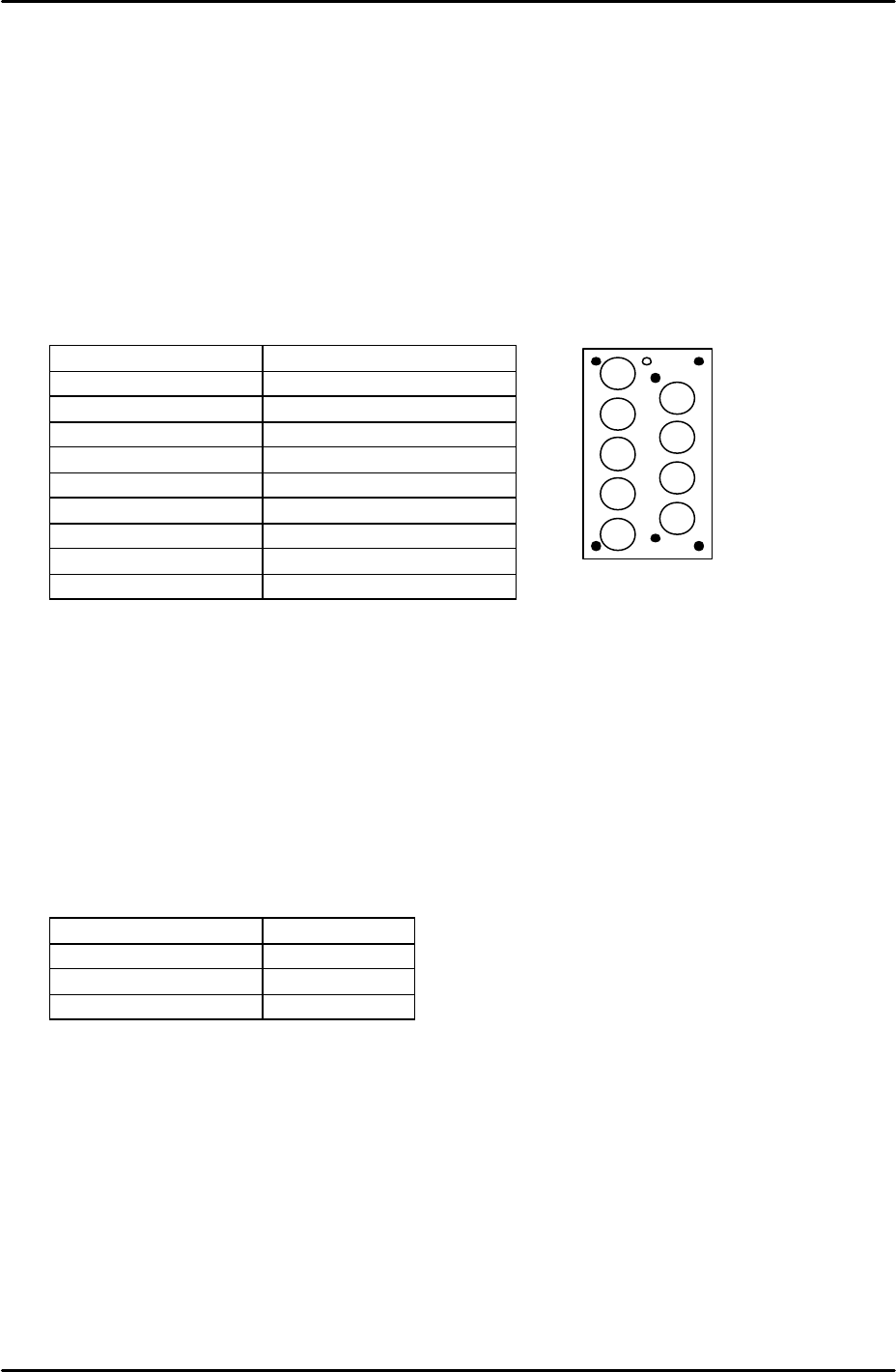
3. Select [Production] – [Nozzle Editor] and configure the nozzle editor entries as described
in the following table:
Nozzle Number Nozzle Diameter (mm)
1 0.7
2 1.0
3 1.3
4 1.8
5 2.5
6 3.7
7 10
8 15
9 20
4. Arrange the nozzles in the nozzle station so that they match the nozzle editor
configuration.
5. Set the conveyor at its maximum width of 356mm.
6. Load empty shelves in the MTU and set magnets on the shelves to block the tray height
check sensor aperture. This has the effect of interrupting the sensor, and thus allows
idling to proceed.
7. Select [Maintenance A] – [Select Mode] and set the mode as detailed in the following
table:
Operation Mode Idle
Production Mode Automatic
Error Handling Error Stop
Acceleration Rate 0.1
8. Check for any mechanical interference in the machine then select [Production] –
[Automatic] – [Start] to commence idling.
9. Check that there are no irregular noises or movements in the machine and then gradually
increase the acceleration rate up to a maximum of 0.7. The acceleration rate of 0.7
should not be exceeded since the present software does not support idling above 70% of
full speed.
10. The machine should be run for at least 12 hours without stopping, and in total for at least
30 hours.
11. After idling is complete check the machine for any irregularities.
2
1
3
4
5
6
7
8
9