xp141-241-341-5.0E.pdf - 第168页
FK-9F98- 29 XP Series Training Text for Service Engineers Edition 5.0 XP241 – Chapter 7 Checking Operation and Accuracy Page 1 of 4 Fuji Machine Mfg. Co., Ltd. Okazaki SMT Equipment Quality Assurance Dept. 7– 1 CS Sectio…

C
C
h
h
a
a
p
p
t
t
e
e
r
r
7
7
O
O
p
p
e
e
r
r
a
a
t
t
i
i
o
o
n
n
a
a
n
n
d
d
A
A
c
c
c
c
u
u
r
r
a
a
c
c
y
y
FK-9F98-29 XP Series Training Text for Service Engineers
Edition 5.0 XP241 – Chapter 7 Checking Operation and Accuracy Page 1 of 4
Fuji Machine Mfg. Co., Ltd. Okazaki
SMT Equipment Quality Assurance Dept.
7–1 CS Section
Chapter 7 – Checking Operation and Accuracy
7.1 Checking idle operation
1. Transmit the idle program “XP2_IDLE” to the machine.
2. Select [Production] – [Select Program] – [XP2_IDLE] – [Download] to bring the program
into the machine foreground.
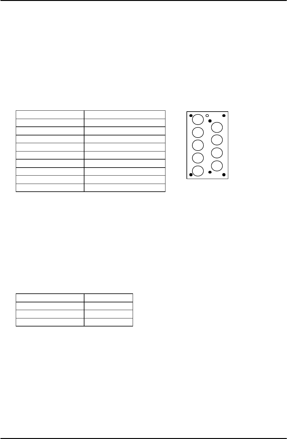
3. Select [Production] – [Nozzle Editor] and configure the nozzle editor entries as described
in the following table:
Nozzle Number Nozzle Diameter (mm)
1 0.7
2 1.0
3 1.3
4 1.8
5 2.5
6 3.7
7 10
8 15
9 20
4. Arrange the nozzles in the nozzle station so that they match the nozzle editor
configuration.
5. Set the conveyor at its maximum width of 356mm.
6. Load empty shelves in the MTU and set magnets on the shelves to block the tray height
check sensor aperture. This has the effect of interrupting the sensor, and thus allows
idling to proceed.
7. Select [Maintenance A] – [Select Mode] and set the mode as detailed in the following
table:
Operation Mode Idle
Production Mode Automatic
Error Handling Error Stop
Acceleration Rate 0.1
8. Check for any mechanical interference in the machine then select [Production] –
[Automatic] – [Start] to commence idling.
9. Check that there are no irregular noises or movements in the machine and then gradually
increase the acceleration rate up to a maximum of 0.7. The acceleration rate of 0.7
should not be exceeded since the present software does not support idling above 70% of
full speed.
10. The machine should be run for at least 12 hours without stopping, and in total for at least
30 hours.
11. After idling is complete check the machine for any irregularities.
2
1
3
4
5
6
7
8
9
FK-9F98-29 XP Series Training Text for Service Engineers
Edition 5.0 XP241 – Chapter 7 Checking Operation and Accuracy Page 2 of 4
Fuji Machine Mfg. Co., Ltd. Okazaki
SMT Equipment Quality Assurance Dept.
7–2 CS Section
7.2 Placement Accuracy Measurement
Side 1 Camera
1. Equipment: 108 Pin Glass board (BVDZ-0200). 108 Pin glass parts (BVDZ-0140). Glass
parts pick up platform for MFU.
2. Transmit the program XP2_S_F to the machine.
3. Select [Production] – [Select Program] – [XP2_S_F] – [Download] to bring the program
into the machine foreground.
4. Select [Production] – [Feeder Data] – and check which device numbers the parts will be
picked up from.
5. Load the glass parts pick up platform in the MFU and set the glass parts on the platform.
6. Select [Maintenance A] – [Select Mode] – and set the mode as detailed in the following
table:
Operation Mode Production
Production Mode Automatic
Error handling Error stop
Acceleration Rate 1.0
7. Check that there is a 15mm diameter nozzle in the nozzle station.
8. Select [Production] – [Nozzle Center Measurement] – [Side 1] – Acceleration rate [1.0] –
[Rotate Center Measurement] and the measurement proceeds. Prior to PAM this
measurement should be carried out at least 5 times.
9. Put double sided “Nitto” tape on the top surface of the glass board where the parts will be
placed. In addition the underside of the board should be covered in green tape so that
when the mark camera reads the marks on the board the background is green.
10. Select [Production] – [Conveyor Width Change] – [Move] to set the conveyor width to the
program value then load the board in the main conveyor.
11. Select [Production] – [Automatic] – [Start] – [START] and the glass parts will be picked up
and placed on the board.
12. Once all the parts have been placed press [Cycle Stop] and exit the production screen.
Select [Maintenance C] – [Glass gauge measurement] – [Start] to measure the placement
accuracy. “Size Big’” should not be selected at this time.
13. When the measurement is complete, press the [Results] tab and then a placing offset can
be made by pressing the [Front Offset] tab.
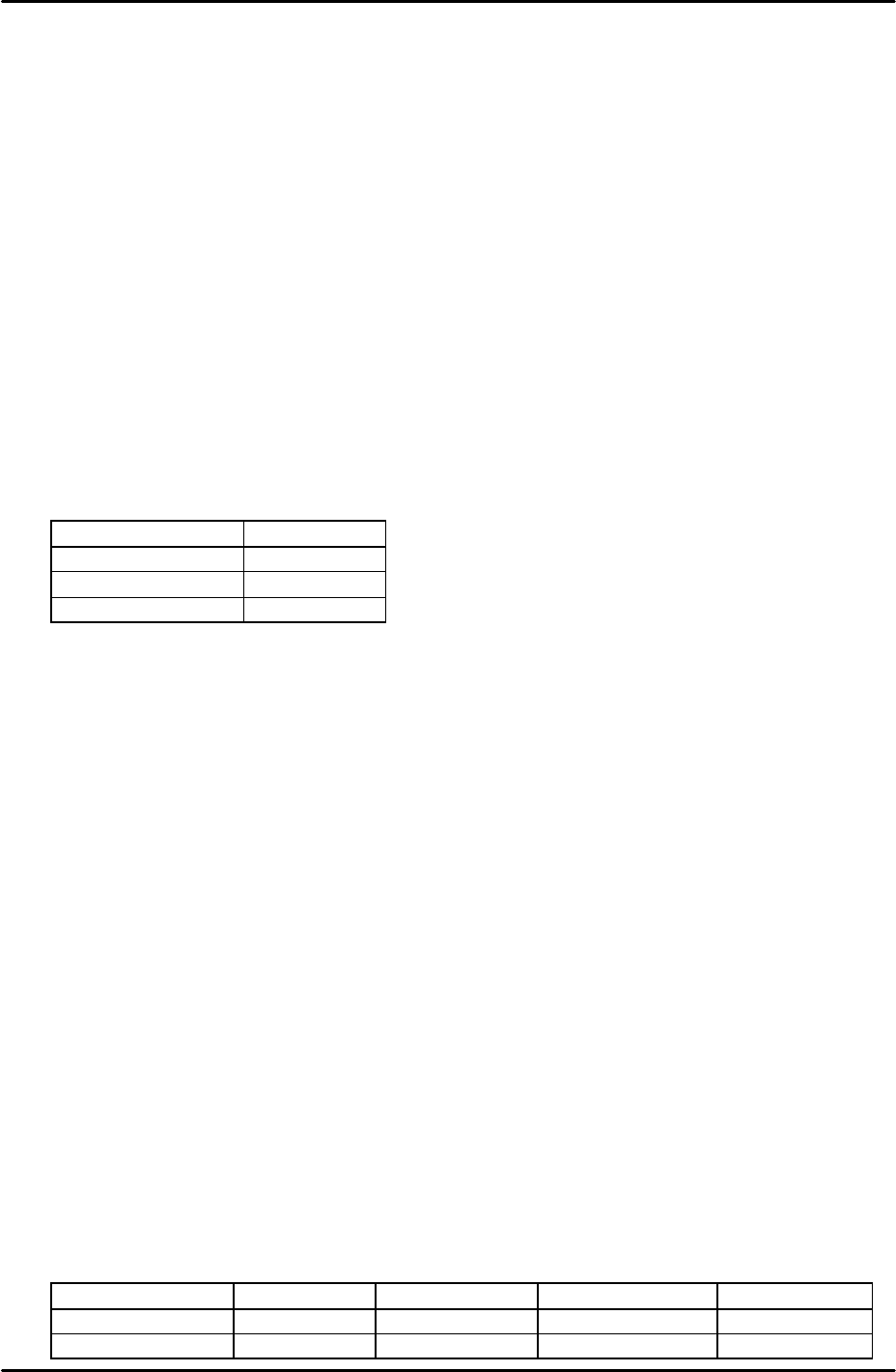
14. Repeat the process until the placement accuracy results are within the tolerances
described in the following table:
Average Maximum Minimum 3 Sigma
X and Y (mm)
+/- 0.010 0.030 -0.030 +/- 0.030
Theta (degrees)
+/- 0.030 Not Specified Not Specified Not Specified